Grounding and Bonding a Small Off-Grid DC System
Equipment grounding versus system bonding versus earthing, floating versus bonded DC negatives, and why local code should override generic advice here.
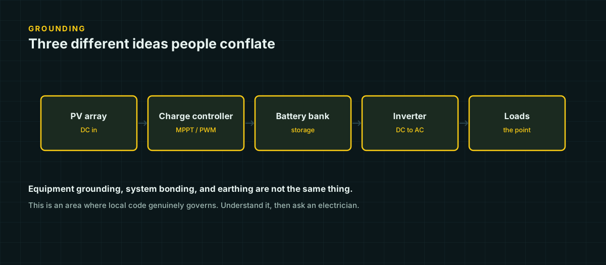
Grounding is the topic where DIY solar advice online is least trustworthy, and it is also the topic where getting it wrong has the least forgiving failure mode. Voltage drop costs you performance. A wrong fuse costs you equipment. A wrong grounding decision on a permitted structure can leave energized metal that a person touches expecting it to be safe.
This article is written with that asymmetry in mind. It explains the concepts — what grounding and bonding actually do, why beginners routinely conflate them, and why a vehicle and a building are not the same problem — so that you can recognize what an installation is doing and have an informed conversation with an electrician or an inspector. It is deliberately not a set of instructions for making the grounding decision yourself on anything connected to a structure. Where local code applies, it is the authority, not this page.
The distinction beginners conflate: grounding versus bonding
“Grounding” gets used as a catch-all term for several different, related jobs. Two of the most commonly confused are described clearly by secondary explainers of NEC Article 690’s grounding provisions:
Bonding is the process of connecting normally non-current-carrying metal parts together — panel frames, the racking system, equipment enclosures, a battery box’s metal chassis — so that if a live conductor accidentally contacts one of them, there is a low-resistance path back to the source. That low-resistance path is what allows a fuse or breaker to see enough fault current to open quickly. Without bonding, a fault to a metal frame can leave that frame energized indefinitely, because there is no path for enough current to flow and trip anything — the frame just sits there live, waiting for a person to complete the circuit through their own body.
System grounding is connecting the electrical system itself to earth, providing a voltage reference and a path that helps limit voltage rise from lightning or other transients. This is a different job from bonding, even though the two are physically connected in most real installations.
Put simply: bonding is about making faults visible to your protection devices so they trip. Grounding is about referencing the system to earth and giving transient energy — lightning, static, switching surges — somewhere to go besides through your equipment or through a person.
| Term | What it connects | Job it does | What fails without it |
|---|---|---|---|
| Bonding | Non-current-carrying metal parts to each other (frames, enclosures, racking) | Gives a fault a low-resistance path back to the source so a breaker or fuse sees enough current to trip | A fault can leave metal energized indefinitely with no path large enough to open a breaker |
| System (earth) grounding | The bonded system to an actual earth electrode | Provides a voltage reference and a path for lightning/surge energy to dissipate into the earth | Transient energy has no defined path and can instead pass through equipment or wiring not designed to carry it |
| Equipment grounding conductor (EGC) | A specific piece of equipment’s metal parts back toward the source | The conductor that physically carries fault current for the bonding job above | The equipment’s bonding has no return path even if the frame itself is connected to something |
| Grounding electrode conductor (GEC) | The system to the grounding electrode itself (rod, foundation electrode) | The conductor that physically carries the earth-reference job above | The system may be internally bonded but never actually referenced to earth |
Notice that each row depends on the one above it actually being in place. A grounding electrode conductor with no bonded equipment behind it protects nothing; bonded equipment with no grounding electrode conductor has fault protection but no earth reference. A complete system needs all four working together, not just whichever one happened to get installed.
Equipment grounding conductor versus grounding electrode conductor
The same secondary sources distinguish two conductors that both get casually called “the ground wire,” and they do different jobs.
An equipment grounding conductor (EGC) provides the fault-current return path described above — it connects a piece of equipment’s non-current-carrying metal parts back toward the source, so a fault trips a breaker or blows a fuse instead of leaving the metal energized.
A grounding electrode conductor (GEC) connects the system to an actual grounding electrode in the earth — a ground rod, a building’s foundation electrode, or similar. GEC sizing in the NEC is governed by its own table, referenced to the size of the largest ungrounded (current-carrying) conductor in the system, and the NEC specifically excludes aluminum as a GEC material.
These are not interchangeable, and a system can have one without functioning correctly if it is missing the other. An array frame that is bonded to other equipment but never connected to an actual earth electrode has fault protection but no lightning/surge reference. A ground rod driven into the earth with nothing bonded to it protects nothing, because there is no path from a fault back to that rod.
Floating versus bonded DC negative: a real design decision
One of the more consequential choices in a DC system’s design is whether the negative conductor is intentionally connected to ground (a “solidly grounded” system) or deliberately kept isolated from ground (a “floating” or ungrounded system, sometimes with a functional ground reference provided through other means).
Both are legitimate, real designs used in commercially available equipment, and the choice changes how the system behaves when a first fault occurs.
In a solidly grounded system, one DC conductor is intentionally bonded to ground. A second, independent fault — current escaping to a grounded metal part on the other conductor — creates a real short circuit that a properly designed ground-fault protection device should detect and interrupt. This design requires that ground-fault detection: without it, a first fault can go completely unnoticed while it sets up conditions for that second, dangerous fault.
In an ungrounded (floating) system, neither DC conductor is intentionally connected to ground. A single fault to ground on one conductor does not, by itself, create a large fault current, because there is no intentional ground reference for it to fault against — but it does mean the system’s actual voltage relative to ground has shifted, silently, in a way that is easy to miss without monitoring for exactly that condition. A second fault, on the other conductor, is what turns that silent condition into a real short circuit.
Modern grid-tied and many off-grid inverters use a functionally grounded or ungrounded approach with the inverter itself providing ground-fault monitoring rather than a solidly bonded conductor — this is a documented, common approach in current transformerless inverter designs. The point for a DIY builder is not to memorize which is “correct” — neither is universally correct — but to recognize that this is an intentional design choice built into your specific charge controller, inverter, or battery management system, and that choice determines what protection scheme the rest of the system needs around it. Check your equipment’s documentation for how it handles DC grounding before assuming either answer.
Array frame bonding and why it matters beyond fault current
Bonding a PV array’s frames, racking, and mounting hardware together, and connecting that bonded system to an equipment grounding conductor, serves the fault-current purpose described above. It is also part of how a system manages lightning and surge exposure, because a bonded, grounded metal structure gives an induced surge a defined path to follow rather than an unpredictable one through whatever wiring happens to offer the least resistance at that instant.
This is also where DIY installations most commonly cut corners, because bonding an array frame produces no visible functional benefit on a normal, fault-free day. A system with unbonded racking will charge the battery and run the loads identically to one with correctly bonded racking — right up until the day a fault or a surge event finds the unbonded path instead of the intended one.
Vehicle chassis-return systems are not the same problem as a building
A common source of confusion is applying building-grounding intuition to a vehicle, van, or trailer electrical system, or the reverse. They are not the same problem, because a vehicle has no practical, continuous connection to earth.
A stationary building sits on or near the actual earth, and its grounding electrode system — a ground rod, foundation electrode, or equivalent — provides a real, low-resistance path into that earth. A moving vehicle does not have this. Its “ground” is the vehicle’s own metal chassis, used as a return conductor for the electrical system’s negative side, referenced to the vehicle itself rather than to earth. This is why vehicle electrical systems are commonly described as “chassis-return” or “chassis ground” rather than “earth-grounded” — the terminology difference reflects a real difference in what the reference point physically is.
This distinction matters practically: hardware, terminology, and code developed for stationary, earth-grounded building systems (the NEC) does not map directly onto a vehicle’s chassis-return system, which is why marine and RV wiring commonly follows ABYC standards rather than the NEC — the underlying grounding and bonding problem the standard is solving is genuinely different, not just differently named.
Why this is where generic advice stops being safe
Three things make grounding and bonding different from the wire-sizing and fuse-sizing topics covered elsewhere on this site:
The failure mode is a person, not just equipment. An overcurrent fault, handled by an oversized fuse, does damage to wire and equipment. An unbonded metal enclosure carrying a fault is potentially energized metal that someone touches, expecting it to be safe because it looks like every other metal enclosure in the room.
Local code genuinely governs, and it genuinely varies. Article 690 of the NEC devotes a full section to PV system grounding and bonding requirements, with specific rules for equipment grounding conductor sizing, grounding electrode conductor sizing, and the conditions under which solidly grounded versus functionally grounded designs are permitted. An authority having jurisdiction can layer additional requirements on top of the base code, and the specific edition of the NEC in force where you are matters, because these provisions have changed materially across editions. There is no single “the rule” that applies everywhere.
A wrong decision here does not announce itself. An undersized wire gets warm. A wrong fuse nuisance-trips or, worse, fails to trip — but at least it fails during a fault, when something has already gone wrong and attention is already on the system. A wrong grounding or bonding decision can sit invisibly correct-looking for years and only reveal itself at the exact moment a fault occurs, which is the worst possible moment to discover it.
What this page is, and what it is not
This page is an explanation of concepts, written so that you can look at a system — yours or someone else’s — and recognize what its grounding and bonding scheme is doing, ask an informed question about it, and understand an electrician’s or an inspector’s answer when you get one.
It is not a decision procedure. It does not tell you whether your specific system should have a floating or bonded DC negative, what size grounding electrode conductor your installation needs, or how to bond your specific array racking correctly. Those are decisions that depend on your equipment’s documentation, your installation type, and the code your local authority having jurisdiction enforces — and for anything connected to a permitted structure, or any system large enough to present real fault current, those are decisions for someone qualified to make with you, not a generic article to make for you.
Sources and further reading
Figures on this page are traceable to the published documents below. Where a standard is referenced, check the edition your local jurisdiction has adopted before relying on it.
- Grounding and Bonding for PV Systems: NEC 690 Part VExpertCESecondary explainer of NEC Article 690 Part V. Source for the equipment-bonding-versus-system-grounding distinction, the definition of a solidly grounded system versus a functionally/ungrounded array with a transformerless inverter, and the equipment grounding conductor (EGC) requirement for array frames.
- Guidelines for designing grounding systems for solar PV installations in accordance with the NECHeatSpringSecondary explainer. Source for the distinction between an equipment grounding conductor (EGC, fault-current return path) and a grounding electrode conductor (GEC, connection to earth via an electrode), and for the statement that GEC sizing follows NEC Table 250.66 based on the largest ungrounded conductor in the system.