DIY Solar Pre-Flight Checklist: What to Verify Before First Power-On
A sequential commissioning procedure for small solar systems: polarity, torque, fuse ratings, energization order, and what to check at one hour, one day, and one week.
Every small solar system gets built once and energized once. The build can be sloppy in a dozen forgivable ways and still work — a slightly long cable run, an ugly cable route, a connector reused twice. Energization is different. It is the one moment where a wrong assumption stops being theoretical and starts being current flowing somewhere it should not.
This is a sequence, not a list. Do the steps in order, because several of them exist specifically to catch a mistake made in an earlier step before it reaches a component that cannot absorb it.
Verify polarity before anything is connected
Before a single permanent connection is made, put a multimeter on every pair of leads that will eventually mate: battery to controller, controller to array, controller to load bus. Confirm positive against positive and negative against negative, and confirm it at the connector, not by trusting the wire color.
The reason this comes first is that reverse polarity is invisible until current flows, and by then it has usually gone through something. A charge controller’s PV input is normally protected against reverse connection by a blocking diode or MOSFET arrangement, but battery-side reverse polarity is a different story — many controllers have little or no reverse protection on the battery terminal, because the design assumes you would never get that one wrong. Assume nothing. A five-second continuity check against a wiring diagram is the cheapest insurance in this entire process.
Torque every lug to the printed value
A crimped or bolted lug connection is a mechanical joint standing in for a piece of solid copper, and its electrical performance depends entirely on how much metal-to-metal contact area is actually loaded.
Under-torqued, the contact area is small. Current still flows, but it flows through a constriction, and that constriction has resistance. Resistance under current is heat — not a large amount at first, but enough to soften the connection further, which shrinks the contact area more, which raises resistance more. This is a runaway loop, and it is why a loose lug that was merely warm on day one can be found scorched months later.
Over-torqued, you get a different failure. Copper strands fracture, threads gall, or a busbar’s threaded insert strips. The connection looks tight and reads fine on a meter today, and then vibration or thermal cycling finishes the job the wrench started.
There is no universal torque number, because it depends on the lug size, the material, and the terminal’s own rating — a busbar, a breaker, and a battery post are not interchangeable specifications. Use the value printed on the lug, in the connector’s datasheet, or in the equipment manual, and use a calibrated torque wrench or torque screwdriver to hit it. If a component ships with no printed torque spec at all, that absence is itself useful information about the manufacturer.
Confirm fuse and breaker ratings match the design, not the drawer
This step exists because of a specific, common failure: the build called for a 50 A Class T fuse, the parts bin had a 60 A ANL fuse left over from another project, and it got installed “for now.” For now becomes forever on a surprising number of systems.
Walk the design again and check every overcurrent device against what the calculation actually called for — not what looked close enough. Two things to check specifically, both covered in more depth on our DC overcurrent protection reference:
- Current rating. Too high and the fuse no longer protects the conductor it’s sized to; too low and it nuisance-trips under normal surge.
- Interrupting rating (AIC). This is the one people skip because it never shows up on the outside of the fuse holder. A lithium bank’s low internal resistance means a dead short can deliver fault current well beyond what a lead-acid-rated fuse can safely interrupt. If the bank is lithium, the fuse at the battery terminal should be rated for it — Class T is the common choice — regardless of what was already in the drawer.
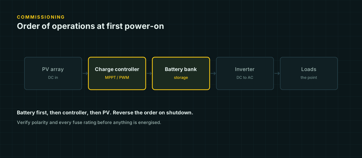
Energization order: battery, then controller, then PV
This is the step most builds get partly right and completely miss the reasoning on. The correct sequence is: connect the battery to the controller first, then connect the array last. When de-energizing, do the reverse — disconnect the PV side first, then the battery.
The mechanism is documented directly in Victron’s own MPPT manual, which instructs users to “always drop PV first on shutdown, and power PV last” on restart. The reason cited is a voltage transient: breaking a DC circuit that is actively delivering current releases the energy stored in that circuit’s inductance and capacitance as a spike, and that spike can exceed the voltage rating of the controller’s internal components. Connecting in the wrong order risks the same thing in reverse — energizing an input path that the controller has not yet initialized to handle.
It is worth being precise here rather than repeating a scarier version of the claim than the evidence supports. Not every controller is destroyed by having PV connected with no battery present — Victron’s own documentation for one of its MPPT models states plainly that operating without a battery “won’t harm the solar charger,” while still calling the configuration unsupported because the unit cannot regulate loads properly without a battery reference. Cheaper controllers, and especially basic PWM units without equivalent input protection, may not be as forgiving. Rather than betting on which category yours falls into, follow the sequence every manufacturer instructs regardless: battery first, PV last, every time you connect or disconnect. It costs nothing and it is correct for every controller, not just the ones that need it.
Measure open-circuit voltages before connecting
Before the array ever reaches the controller, measure its open-circuit voltage (Voc) directly at the combiner or array leads, with a meter, in whatever conditions exist that morning.
Cold weather raises PV voltage. A silicon module’s open-circuit voltage rises as cell temperature drops, following roughly:
Voc(cold) = Voc(STC) × [1 + (Tcell − 25°C) × (tempco_Voc / 100)]Typical crystalline-silicon Voc temperature coefficients run around −0.25 to −0.35 %/°C — negative, meaning voltage rises as temperature falls below the 25 °C standard test condition. A string of modules whose combined nameplate Voc is comfortably under a controller’s maximum input voltage at 25 °C can close that margin substantially on a cold, clear morning, and series strings compound the effect linearly across every module.
Measuring Voc before connection tells you two things at once: whether your as-built wiring matches the expected series/parallel configuration (a miscounted series string reads as a voltage that does not match the math), and whether today’s actual voltage — not the datasheet number — sits safely under the controller’s rated input. If it does not, the fix is before energization, not after a controller has already seen an overvoltage event.
Set the charge controller’s battery-chemistry profile first
Every multi-chemistry controller has a setting for what kind of battery it is charging, and that setting is not cosmetic — it changes the actual absorption and float voltages the controller targets.
The gap between chemistries is larger than it looks on a spec sheet. At 12 V nominal, Victron’s own datasheets put AGM absorption around 14.2–14.9 V and gel absorption lower, around 14.1–14.4 V. A charger left on an AGM profile chronically overcharges a gel battery — gassing it, drying its electrolyte, and shortening its life — while a charger set for gel undercharges an AGM bank and never quite gets it to full. LiFePO4 tolerates neither lead-acid curve well: its absorption voltage and its tolerance for time spent at absorption are both different from lead-acid chemistry, and most lithium battery manufacturers specify their own controller settings explicitly.
Confirm the profile against your specific battery’s datasheet, not against the controller’s factory default, before the first charge cycle begins. This takes two minutes in the controller’s menu and it is the single easiest mistake to have made silently for months.
First-charge monitoring: three checkpoints, three different failure classes
Once the system is live, do not walk away. Watch it, and watch it at three specific intervals, because each one is tuned to catch a different kind of mistake.
| Checkpoint | What to check | What it catches |
|---|---|---|
| First hour | Controller charge state and current, any unexpected heat at lugs/fuses, battery voltage tracking upward as expected | Wiring mistakes: reversed polarity that got past your check, an undersized conductor running hot, a fuse rated wrong for the actual current |
| First day | Whether the controller reaches absorption voltage at all, ambient and enclosure temperature, whether any connection is warmer than its neighbors | Charge-profile mismatches, thermal problems from poor ventilation or an undersized enclosure, a controller that cannot push enough current to ever leave bulk stage |
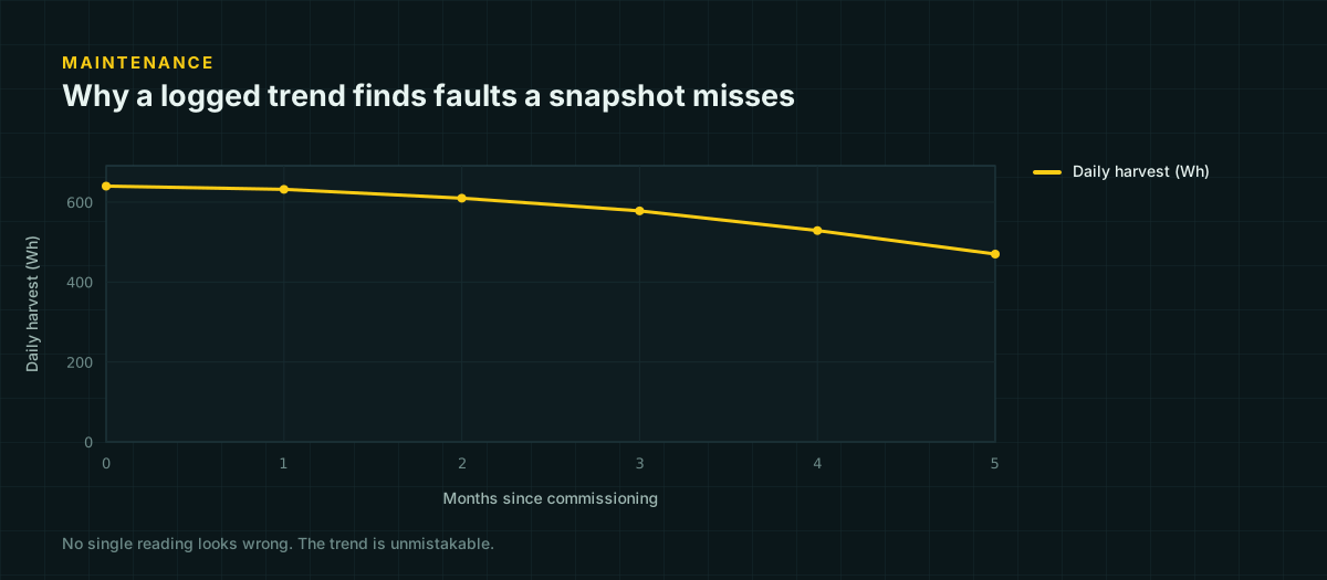
| First week | Trend in daily harvest versus expected, whether float voltage holds steady overnight, whether any lug has loosened (recheck torque) | Connections that were fine when tightened but loosen under the thermal cycling of real daily use; a slow developing fault that a single measurement would miss |
The one-hour check is about catching an outright error. The one-day check is about catching a system that runs but is not actually configured correctly. The one-week check is the one people skip, and it is the one that catches the fault every experienced builder has been burned by at least once: a connection that read perfectly fine on day one and had already started drifting by day five, because thermal cycling — the daily expansion and contraction of a metal joint as current and ambient temperature rise and fall — works slowly and only shows up as a trend, not a single bad reading.
Before you flip the switch
Nothing on this page substitutes for your specific equipment’s manual. Controllers, inverters, and batteries vary enough in their protection circuitry and their required settings that a generic checklist can tell you what to verify but not always what value is correct for your hardware — that number belongs on the label, in the datasheet, or in the manual that came in the box. If the system is permanent, connected to a structure, or built around a battery bank large enough to deliver serious fault current, have the wiring reviewed by someone qualified before first power-on. The checklist above is what to verify; it is not a substitute for knowing why each verification exists, which is the actual point of doing it in order.
Sources and further reading
Figures on this page are traceable to the published documents below. Where a standard is referenced, check the edition your local jurisdiction has adopted before relying on it.
- Correct sequence to power up MPPT controllersVictron Energy Community ArchiveQuotes Victron's own MPPT manual (section 6.5): disconnect PV first on shutdown, connect battery first on restart. Cites voltage-spike damage from breaking a loaded PV circuit.
- Can MPPT charge controller be used without a battery?Victron Energy Community ArchiveQuotes the Victron 250/70 manual stating operating without a battery will not harm that specific charger, while still calling the configuration unsupported. Used to avoid overstating a universal damage claim.
- 12.8 & 25.6 Volt Lithium Iron Phosphate Batteries Smart — datasheetVictron EnergySource for LiFePO4 charge acceptance and temperature limits used in the first-charge section.
- Gel and AGM Batteries — datasheetVictron EnergySource for the AGM (14.2-14.9 V) versus gel (14.1-14.4 V) absorption voltage figures at 12 V nominal.
- Matching Victron Energy solar modules to the new MPPT charge regulatorsVictron EnergySource for the cold-weather Voc rise formula and temperature coefficient behavior.