Sizing an Inverter: Why the Biggest One Is Usually the Wrong Choice
Continuous versus surge rating, the hidden cost of idle draw, and why a 2000 W inverter can waste more power than it delivers on a small solar system.
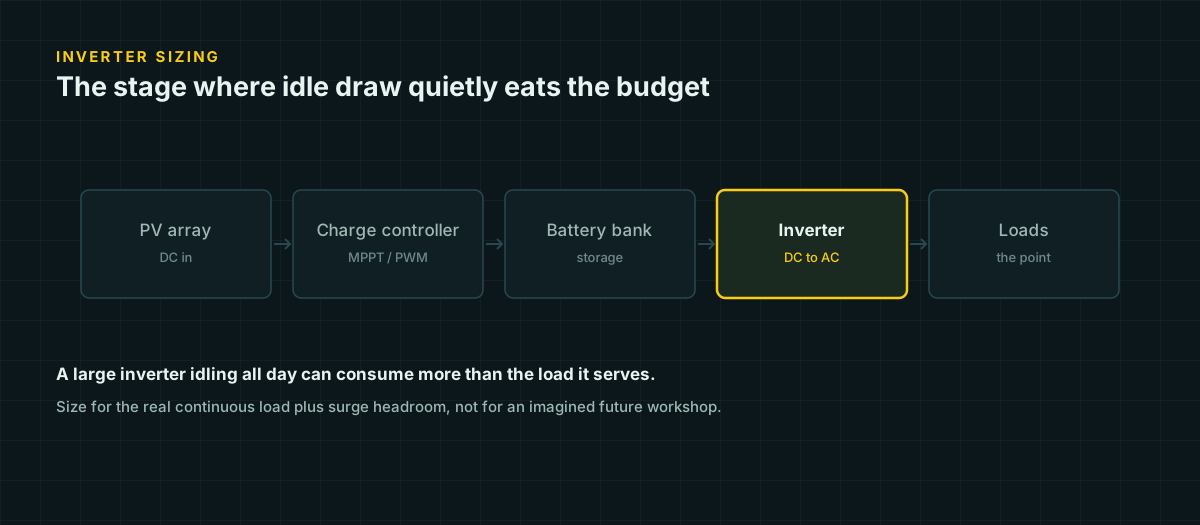
The instinct when buying an inverter is to round up. A bigger number on the box feels like margin, and margin feels safe. For a shed, cabin, or van system, that instinct is usually wrong, and it is wrong in a specific, measurable way: an oversized inverter has a bigger appetite even when it is doing nothing.
An inverter is not a passive pipe that current flows through only when a load calls for it. It runs a switching circuit, a control board, and a transformer or high-frequency converter continuously whenever it is powered on, and every one of those draws current whether or not anything is plugged into the outlet. Sizing an inverter well means matching it to the loads it actually serves — both the steady ones and the ones that spike hard for a fraction of a second — and understanding that the inverter itself is one of the loads on your system, all day, every day it is switched on.
This page works through the numbers: continuous versus surge rating, what an idle inverter actually costs over a day, why pure sine and modified sine inverters are not interchangeable, why efficiency looks worse at partial load, what a large inverter does to your DC wiring and fusing, how it interacts with low-voltage cutoff, and when running two smaller inverters beats running one large one.
Continuous rating and surge rating are different specs
A nameplate wattage on an inverter is its continuous rating: the load it can supply indefinitely without overheating or shutting down. Most inverters also publish a surge or peak rating, sometimes for 3 seconds, sometimes for less, which is meaningfully higher — often double the continuous figure.
Both numbers matter, but they matter for different loads. A resistive load — an incandescent bulb, a resistive heater, most LED drivers — draws close to the same current from the instant it switches on to the instant it switches off. Its running current is close to its starting current, so continuous rating is what matters.
A load with a motor, compressor, or pump behaves completely differently. An induction motor at rest has almost no back-EMF to oppose the current flowing into its windings, so the current at the moment of startup is dominated by the winding resistance alone — far lower impedance than the motor presents once it is spinning and generating a counter-voltage. The result, well documented across motor engineering references, is that induction motors and compressors commonly draw 3 to 7 times their running current for a fraction of a second at startup, and refrigeration compressors in particular can sit at the high end of that range because the compressor has to overcome trapped refrigerant pressure before it can turn.
This is the number that should size your inverter, not the running wattage on the appliance label. A chest fridge that runs at 90 W can have a startup surge of 400–600 W. A well pump rated 500 W running might briefly demand 2,000 W or more. If the inverter’s surge rating cannot cover that spike, it will fault or shut down at the exact moment the compressor tries to start — repeatedly, since the compressor will keep trying.
The idle draw problem
Here is the part that catches people off guard: an inverter that is switched on but serving nothing still draws power. Two real Victron Phoenix datasheets make the scale of this concrete.
| Model | Continuous rating | Peak rating | Zero-load power (12 V) |
|---|---|---|---|
| Phoenix 12/375 | 300 W | 700 W | 5.6 W |
| Phoenix Compact 12/2000 | 1,600 W (2,000 VA) | 4,000 W | 9 W |
Notice that the 2,000 VA unit is marketed by its VA rating, but its actual continuous watt rating at 25 °C is 1,600 W — the two numbers are not the same thing, and the gap between them is another reason to read a datasheet rather than a box label.
Now put a small, steady load on both units and see what a day actually costs.
Suppose a 40 W load — a router, a camera system, a small fridge control board — runs for 6 hours a day, and the inverter powering it is left switched on for the full 24 hours because nobody wants to walk out and flip a switch every time the load needs to run.
Load energy = 40 W × 6 h = 240 Wh
Idle tax (300 W unit) = 5.6 W × 24 h = 134.4 Wh
Idle tax (2000 VA unit) = 9 W × 24 h = 216 Wh| Load energy | Idle tax | Total daily draw | Idle as % of total | |
|---|---|---|---|---|
| Phoenix 12/375 (300 W) | 240 Wh | 134.4 Wh | 374.4 Wh | 36% |
| Phoenix Compact 12/2000 | 240 Wh | 216 Wh | 456.0 Wh | 47% |
The larger inverter’s idle draw alone — 216 Wh — is nearly as large as the 240 Wh the load actually used. Step up one more size class, to the same manufacturer’s 12/3000 (zero-load power 20 W), and the idle tax over 24 hours is 480 Wh: more energy than the load consumed, spent by an inverter that spent all day doing nothing useful. This is not a hypothetical edge case — it is what happens to anyone who buys inverter capacity for a future they have not built yet and leaves it running.
The fix is not to avoid inverters. It is to size the continuous rating close to the loads you actually run most of the time, and to treat a large reserve of surge capacity as a separate decision from a large reserve of continuous capacity.
Pure sine versus modified sine: what actually breaks
A pure sine inverter synthesizes a smooth sinusoidal waveform close to what utility power looks like. A modified sine inverter — more accurately a modified square wave — approximates it with a stepped waveform: a flat plateau at positive voltage, a gap near zero, a flat plateau at negative voltage. It is cheaper to build because it needs less switching and filtering hardware, and for purely resistive loads, it works fine.
The failure mode is specific, not vague. A stepped waveform carries substantial odd-harmonic content — extra energy at 3×, 5×, 7× the fundamental frequency — that a true sine wave does not have. Two classes of load are sensitive to that harmonic content for physical reasons:
- Anything with an iron-core transformer or motor winding. Core losses from eddy currents and hysteresis scale with frequency, so the harmonic content in a modified sine wave is dissipated disproportionately as heat inside the transformer or motor, not as useful work. A wall-wart transformer, a microwave’s transformer, and an AC induction motor can all run measurably hotter on modified sine than on the same RMS voltage of pure sine, and some fail from that added heat over time.
- Anything that senses the waveform itself, not just its RMS value. Some variable-speed motor controls, some dimmer circuits, and some equipment with zero-crossing detection read the shape of the AC cycle to time their switching. A stepped wave has a different — and less predictable — zero-crossing behavior than a sine wave, which can cause flickering, buzzing, or outright malfunction.
Battery chargers with capacitive-input switching supplies, some laser printers, and certain medical devices with heated components (CPAP humidifiers are the commonly cited example) are also frequently flagged by manufacturers as requiring pure sine input — check the specific appliance’s manual rather than assuming.
For a system running electronics, chargers, and anything with a motor, pure sine is worth the price difference. For a system running only resistive loads — simple incandescent or resistive heating elements — modified sine is a legitimate way to save money, provided nothing on the circuit ever changes.
Efficiency is worst exactly where small systems live
Every inverter datasheet publishes a maximum efficiency figure — typically 85–95% for the small to mid-size units used in off-grid systems. What most datasheets do not publish is a full efficiency curve across the load range, but the underlying physics explains why that single number is optimistic for small loads.
An inverter’s losses split into two categories. Fixed losses — control-circuit power, transformer core losses, gate-drive current for the switching devices — happen continuously regardless of how much power is passing through, which is exactly the idle draw discussed above. Variable losses — conduction losses in the switching devices and windings — scale roughly with the square of current, so they grow fast as load increases.
At very light load, fixed losses dominate the loss budget because there is not much output power to divide them by; efficiency is poor. As load rises, fixed losses become a shrinking fraction of the total while variable losses are still small, so efficiency climbs toward the datasheet’s peak figure — typically somewhere in the middle of the inverter’s rated range. Push load higher still, toward the inverter’s continuous limit, and variable losses grow fast enough that efficiency starts to fall again. The practical result is a hump-shaped curve, not a flat one, and an inverter running a load that is a small fraction of its rating — the router-and-camera example above — never gets near the number printed on the box.
What the DC input current means for wire and fuses
An inverter’s AC output current is only part of the picture. What actually needs a wire and a fuse is the DC input current, and low system voltage inflates it dramatically.
I_DC = P_AC / V_DC (ignoring conversion loss)A 1,500 W load draws:
- 125 A at 12 V
- 62.5 A at 24 V
- 31.25 A at 48 V
Compare that to the same 1,500 W drawn from a 120 V AC branch circuit: 12.5 A. The 12 V DC input current is 10 times the equivalent AC current for the identical delivered power, purely from Ohm’s law. Add the inverter’s own conversion loss — a realistic 90% efficiency — and the DC input for that same 1,500 W AC output rises to 1,667 W, or 138.9 A at 12 V.
That current has to travel through real copper between the battery and the inverter, and it decides two things at once:
- Ampacity. Per the NEC Table 310.16 figures on our DC wire ampacity page, even 2/0 AWG copper at a 90 °C insulation rating is only good for 195 A, and 1/0 AWG is 170 A — either is workable for 139 A, but 8 AWG or 10 AWG, which would be plenty for a 15 A branch circuit, is nowhere close.
- Voltage drop. Our voltage drop tables top out at 100 A in the published columns; 139 A is past the edge of what the 12 V table even shows, at 3% drop. This is exactly the scenario that pushes serious inverter installations to 24 V or 48 V battery banks — the same 1,500 W load at 48 V is 31.25 A, a current the wire and the fuse can actually handle without turning into a heater.
Fuse or breaker sizing follows the same logic: a DC overcurrent device is commonly sized at roughly 125–150% of the continuous current the circuit is expected to carry, sized to protect the wire’s ampacity rather than the inverter’s peak draw. Undersize the wire for the actual DC current and you either trip the fuse under normal use or, worse, run a wire hot enough to degrade its insulation over time.
Low-voltage cutoff and voltage drop compound each other
Every inverter has a low-voltage cutoff (LVC) — a battery voltage below which it shuts down to protect the battery from over-discharge. That cutoff is measured at the inverter’s own DC input terminals, not at the battery.
If there is meaningful voltage drop between the battery and the inverter, the inverter sees a lower voltage than the battery’s actual state of charge would suggest, and the gap gets worse under load — exactly when current, and therefore drop, is highest. A battery sitting at a real 12.3 V under moderate load might present only 11.9 V at the inverter’s terminals after a 0.4 V drop across an undersized cable. If the inverter’s LVC is set at 11.5 V, that is uncomfortably close, and the moment a motor load spikes the current for its startup surge, the drop spikes with it — a battery that has real capacity left can trip the inverter’s LVC during exactly the highest-current moment of its operation, which is often the worst possible time to lose power to a compressor or pump.
This is one more argument for sizing wire to the voltage-drop standard, not just the ampacity standard, on the run between battery and inverter — see the voltage drop tables for how much length that buys you at a given current and wire size.
When two small inverters beat one large one
The idle-draw math above points to a practical design pattern: split the job instead of buying one inverter sized for the worst case.
A small, efficient inverter — sized close to the steady, always-on loads like a router, a security camera, or a fridge control board — stays switched on continuously and pays a small idle tax, on the order of 5–6 W in the Victron data above. A second, larger inverter, sized for the occasional big or motor-driven load — power tools, a microwave, a well pump — stays switched off except when that load is actually needed, so its much larger idle draw is paid for minutes at a time instead of 24 hours a day.
Going back to the earlier numbers: keeping the 40 W steady load on the 300 W unit instead of the 1,600 W unit saves 81.6 Wh a day in idle overhead alone (216 Wh − 134.4 Wh), without touching the load itself. Over a year that is roughly 30 kWh — a meaningful fraction of a small system’s total battery throughput, recovered by choosing the right-sized box for the job the box actually does most of the time.
The tradeoff is complexity: two inverters means two sets of wiring, two disconnects, and two failure points to maintain. For a system with one dominant steady load and one occasional heavy load, it is usually worth it. For a system with a single load profile that does not split cleanly, one correctly-sized inverter — sized to continuous load with surge headroom for the worst motor start, not sized to “biggest I might ever need” — remains the simpler and often cheaper answer.
Sources and further reading
Figures on this page are traceable to the published documents below. Where a standard is referenced, check the edition your local jurisdiction has adopted before relying on it.
- Inverters 1200 VA – 5000 VA — datasheetVictron EnergySource for continuous/peak power, max efficiency, and zero-load power figures for the 1200–5000 VA Phoenix range, including the 12/2000 and 12/3000 models used in the worked examples.
- Inverters VE.Direct 250 VA – 1600 VA — datasheetVictron EnergySource for the 12/375 model's 300 W continuous rating, 700 W peak rating, and 5.6 W zero-load power figure used in the worked example.