How to Size a Solar Charge Controller for a Small Off-Grid Project
Size a charge controller by array current and array voltage, including the cold-weather Voc rise that turns a nameplate-safe array into an overvoltage fault.
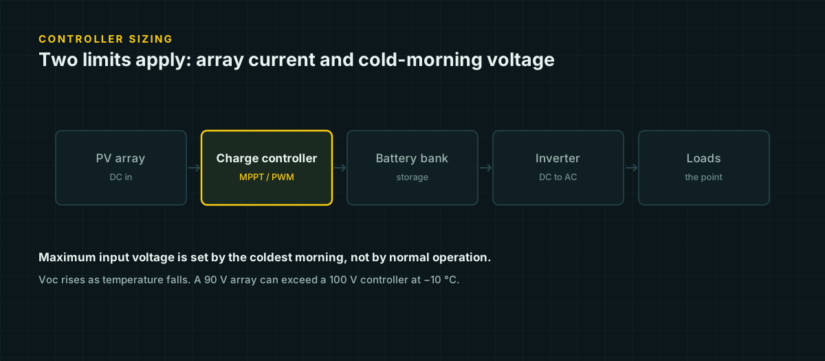
A charge controller has a rated current and a rated voltage, and a surprising number of small builds only check one of them. The current rating gets attention because it is the number people shop by — “40 A controller” sits right there in the product name. The voltage rating gets ignored because the nameplate math looks safe: panels rated 90 V, controller rated 100 V, 10 V of headroom, done. That headroom can disappear on a cold, clear morning before the math has even occurred to anyone.
Both ratings are hard limits, and they fail in different ways. Exceed the current rating and the controller generally just clips or throttles — annoying, wasteful, rarely catastrophic. Exceed the voltage rating and you can destroy the controller outright, sometimes on the first cold sunrise after installation. This guide covers both constraints as separate problems, because treating them as one leads people to check the easier one and skip the other.
We’re assuming a small off-grid system: a shed, a cabin, an RV, or similar — one array, one controller, one battery bank. Grid-interactive systems, multi-MPPT commercial installs, and anything requiring a permit are beyond what this page covers; talk to a licensed installer for those.
Sizing by array current
Start with what the array can produce, not what it’s rated for. A PV module’s short-circuit current (Isc) is a lab number measured at standard test conditions, and real arrays can briefly exceed it — edge-of-cloud lensing and snow reflection both increase irradiance above the 1,000 W/m² standard. NEC 690.8 exists to account for that.
690.8(A) — maximum circuit current. Multiply the module’s rated Isc by 1.25, then by the number of parallel strings.
I_max = I_sc × 1.25 × (number of parallel strings)690.8(B) — conductor and overcurrent sizing. Multiply that result by 1.25 again, because the PV output circuit is treated as a continuous load.
I_conductor = I_max × 1.25Worked example
Suppose four 100 W, 12 V-nominal modules rated Isc = 5.8 A, wired as two parallel strings of two panels in series (2S2P), feeding an MPPT controller on a 12 V battery.
690.8(A): 5.8 A × 1.25 × 2 strings = 14.5 A
690.8(B): 14.5 A × 1.25            = 18.1 A
The PV source conductors need at least 18.1 A of ampacity after derating, and the overcurrent device is sized to the next standard rating that still protects them — commonly 20 A. This is the same 156 percent logic (1.25 × 1.25) covered in more depth on our DC fuse and breaker sizing page, which also covers where the protection device physically belongs in the circuit.
What this means for the controller itself
690.8 sizes the wire and the fuse. It doesn’t automatically size the controller, but the same 690.8(A) figure — the array’s maximum continuous current, before the second 1.25 — is the number manufacturers generally want you to compare against a controller’s rated input current. In the example above, that’s 14.5 A. A controller rated for 15 A input is already running near its ceiling on paper; one rated for 20-30 A gives working headroom for panel tolerance, dust, and reflection off snow.
Sizing by array voltage
This is the constraint that gets skipped, because the nameplate numbers look conservative and the failure mode is invisible until a cold morning exposes it.
A PV module’s open-circuit voltage rises as the cell gets colder — the opposite of what intuition suggests, since colder usually means “less energy.” Voc is a voltage, not a power output, and the semiconductor physics behind it produces higher voltage at lower temperature even though current (and therefore power) drops. The manufacturer’s temperature coefficient of Voc quantifies exactly how much.
Voc(cold) = Voc(STC) × [1 + (Tcell − 25) × (tempco_Voc / 100)]Tcell is in °C, tempco_Voc is the manufacturer’s coefficient in %/°C (a negative number for crystalline silicon), and 25 °C is the standard-test-condition reference temperature. Two independent sources — a Victron engineering blog and a Penn State University course page — describe the identical formula, which is a reasonable amount of confirmation for something you’re about to base a purchase on.
The temperature to use is the cell temperature, not the air temperature you’d check on your phone. But at dawn, before the sun has warmed anything, the panel hasn’t picked up any irradiance heating yet — cell temperature and ambient air temperature are close to equal. That is precisely why cold mornings, not cold afternoons, are when Voc peaks: minimum ambient temperature coincides with minimum cell temperature, right as the array starts producing.
Worked example: the failure hiding in the nameplate math
Suppose the same illustrative 100 W module, rated Voc(STC) = 22.5 V with a manufacturer Voc temperature coefficient of −0.34 %/°C (a figure Victron uses in its own worked example, and within the −0.24 to −0.31 %/°C range independently confirmed across three real crystalline modules’ datasheets). Four of these modules are wired in series, feeding a controller rated for a 100 V maximum input.
Nameplate check: 22.5 V × 4 = 90 V. Ten volts of headroom against the 100 V limit — looks fine.
Now check it cold. Suppose the site sees a −10 °C (14 °F) morning low, not an unusual reading across much of the northern-tier US or southern Canada in winter, and at sunrise the cell temperature is close to that ambient value:
Voc(cold) = 22.5 × [1 + (−10 − 25) × (−0.34 / 100)]
          = 22.5 × [1 + (−35) × (−0.0034)]
          = 22.5 × 1.119
          = 25.18 V per module

String Voc(cold) = 25.18 × 4 = 100.71 V
The string exceeds the controller’s 100 V limit by about 0.7 V on that one cold morning, despite ten volts of apparent nameplate margin. Go a little colder — say −20 °C — and the string climbs past 103.7 V. This is the mechanism behind “the controller is rated 100 V and my panels are 90 V is a failure waiting for a cold morning.” The nameplate comparison and the real comparison are different numbers, and only one of them is the one that matters when the controller actually turns on.
NEC 690.7 and where “lowest expected ambient” comes from
NEC 690.7 is the code section governing maximum PV system voltage — the rule that the calculation above exists to satisfy. In broad terms (we could not verify the current-edition NFPA 70 text directly, since it is copyrighted and not freely published; NEC 690.7 details here come from a secondary compliance-guide explainer), maximum system voltage is the sum of series-module Voc, corrected for the lowest expected ambient temperature at the site — not an arbitrary cold snap, but a specific engineering figure.
That figure conventionally comes from the ASHRAE Extreme Annual Mean Minimum Design Dry Bulb Temperature for the nearest weather station, a published climate design value used across HVAC and electrical design generally. Manufacturer temperature coefficients — what we used above — are the preferred method when available. NEC also publishes a standardized correction-factor table (Table 690.7(A)) for use when a manufacturer coefficient isn’t available; we’re not reproducing its exact factors here since we could not verify them against current primary text, and the manufacturer-coefficient method is more precise anyway.
The practical takeaway: look up your own site’s design minimum temperature (an HVAC contractor’s Manual J documentation, a local ASHRAE table, or your jurisdiction’s electrical inspector will have it) rather than guessing at a round number, and rerun the formula above with that value before you buy a controller close to its voltage ceiling.
Array oversizing and output current limiting
A controller’s input current rating and a controller’s actual behavior under an oversized array are two different things, and this is where a lot of unnecessary hesitation happens. MPPT controllers generally clip: if the array can produce more current than the controller’s rated maximum, the controller simply doesn’t draw more than its rating, and the excess capacity goes unused rather than causing damage. Because of that, community guidance from Victron’s own user forum describes oversizing a PV array to roughly 130 percent of the controller’s rated wattage as a common and generally acceptable practice — panels rarely operate at their full nameplate rating except for an hour or so around solar noon on a clear day, so headroom is often idle capacity rather than wasted capacity.
What oversizing does not override are the two hard limits covered above: the array’s cold Voc must never exceed the controller’s maximum input voltage, and the array’s Isc-based current (from the 690.8(A) calculation) must not exceed the controller’s maximum input current rating. Oversizing wattage by adding more parallel strings raises Isc directly; oversizing by adding more series modules raises Voc directly. Check which axis you’re expanding along.
Matching controller output to the battery
The controller’s output-side current rating is a different design question from either of the above, and it’s easy to lose track of because all three numbers look similar. What the array can deliver and what the controller outputs both need to be checked against what the battery can actually absorb without a mismatch wasting the whole exercise.
Charge acceptance varies enormously by chemistry — LiFePO4 accepts roughly 0.5C continuously and up to 1C briefly, while a flooded lead-acid bank is limited to roughly C/10 to C/8. A 40 A controller feeding a 100 Ah flooded battery capped near 10-13 A is delivering three to four times what the battery can use; the extra capacity does nothing once the battery’s absorption stage kicks in. Full figures and sourcing for each chemistry’s charge acceptance are on our battery chemistry comparison page.
A sizing checklist before you buy
| Check | What you need | Where it comes from |
|---|---|---|
| Array max current | Isc × 1.25 × parallel strings (690.8(A)) | Module datasheet |
| Conductor/OCPD current | Above × 1.25 again (690.8(B)) | Same, plus derating tables |
| Nameplate string voltage | Sum of series-module Voc(STC) | Module datasheet |
| Cold string voltage | Voc(STC) × [1 + (Tcell − 25) × tempco/100] per module, summed | Datasheet tempco + site design minimum temp |
| Controller input current rating | ≥ 690.8(A) result, more if oversizing | Controller datasheet |
| Controller input voltage rating | > cold string voltage, with margin | Controller datasheet |
| Battery charge acceptance | C-rate × battery Ah | Battery datasheet |
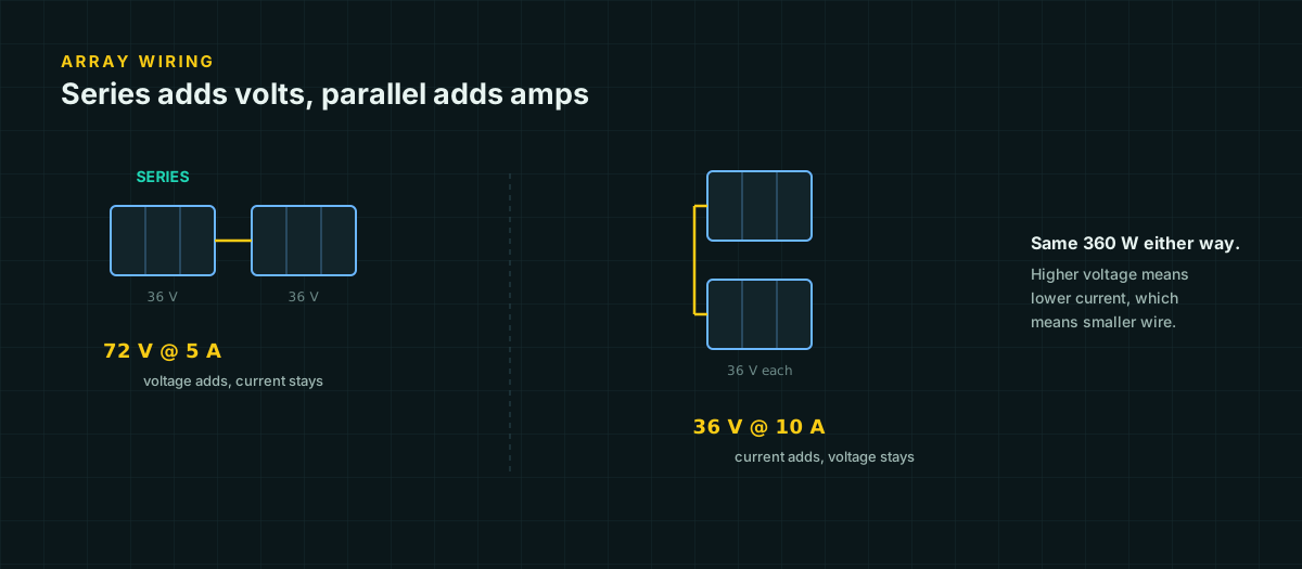
If any row fails, the fix is usually cheaper before the array is mounted than after: fewer modules per series string lowers cold Voc; more parallel strings (with proper fusing once you reach three or more — see the series versus parallel wiring guide) raises current instead of voltage; a controller one size up removes the argument entirely.
What this doesn’t cover
This page assumes identical modules in each string — mixing panels with different Voc, Isc, or Vmp inside the same series string introduces mismatch losses covered separately. It also assumes a single controller and a single array; multiple MPPT trackers, battery banks wired for higher system voltages, or anything feeding back into utility service is design and permitting territory for a licensed installer, not a DIY sizing checklist. And every number here is a planning figure — the controller’s actual datasheet limits, not this article, are the final authority for your specific hardware.
Sources and further reading
Figures on this page are traceable to the published documents below. Where a standard is referenced, check the edition your local jurisdiction has adopted before relying on it.
- Matching Victron Energy solar modules to the new MPPT charge regulatorsVictron EnergySource for the cold-weather Voc formula and the -0.34%/°C worked-example coefficient used in this article's illustrative panel.
- Voltage design — AE 868: Commercial Solar Electric SystemsPenn State University, Department of Architectural EngineeringIndependent confirmation of the same cold-weather Voc formula.
- How to Calculate Wire Size and Amps: NEC 690.8(B)Mayfield RenewablesSource for the NEC 690.8(A) and 690.8(B) 125% factors used in the current-sizing example.
- NEC 690.7 Solar Voltage Limits: Calculation Methods and RequirementsSurgePVSecondary explainer, not the NFPA 70 text itself, which is copyrighted and was not directly accessible. Does not cite a specific NEC edition; describes the ASHRAE-based method for finding lowest expected ambient temperature.
- MPPT Oversizing & CalculatorVictron Energy Community ArchiveCommunity guidance from Victron's own forum, not an official manual. Cited for the general oversizing practice and the hard Voc/Isc limits that oversizing does not override.