Wiring Panels in Series or Parallel: Voltage, Current, and Shade Tradeoffs
How series and parallel panel wiring change voltage, current, wire size, and shading behavior, and when parallel strings need their own fuses.
Every panel added to an array has to be wired in somehow, and the choice between series and parallel isn’t just a wiring-diagram preference — it changes the array’s operating voltage, its operating current, the wire gauge that keeps losses acceptable, how badly a single shaded panel hurts total output, and whether the array needs string-level fuses at all. Getting this decision right before running cable saves you from re-terminating a fully mounted array later.
What each connection actually does
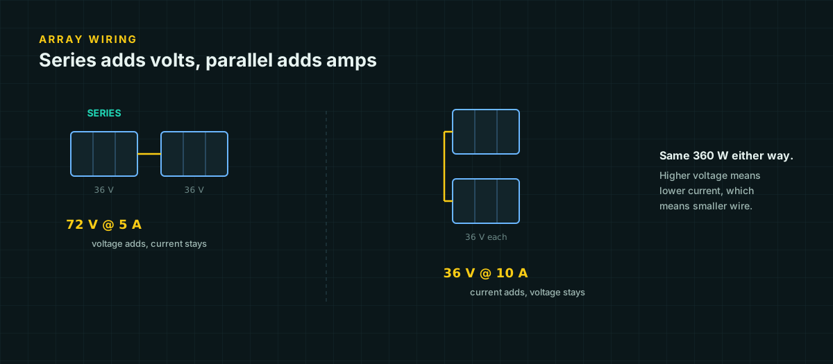
Wire two identical modules in series — positive lead of one to negative lead of the next — and the pair’s voltage adds while current stays at a single module’s rating. Two 18 V-Vmp, 5.56 A modules in series become a 36 V, 5.56 A source.
Wire the same two modules in parallel — positive to positive, negative to negative — and the reverse happens: current adds while voltage stays at a single module’s rating. The same two modules in parallel become an 18 V, 11.12 A source.
Both deliver the same 200 W (minus real-world losses). The difference is entirely in how that power is packaged, and that packaging decision cascades into everything downstream.
Wire size and voltage drop
Voltage drop is proportional to current, and higher system voltage for the same power means lower current. That relationship compounds, because voltage drop as a percentage of system voltage is affected twice over: once because current drops, and again because the reference voltage you’re comparing against is larger.
Worked example
Take those same two 100 W modules feeding a controller 30 feet away, wired with 10 AWG copper (1.21 Ω per 1,000 ft, or 0.00121 Ω/ft, from published copper resistance figures).
Parallel (18 V, 11.12 A):
V_drop = 2 × 30 ft × 11.12 A × 0.00121 Ω/ft = 0.807 V
drop % = 0.807 / 18 × 100 = 4.5%
Series (36 V, 5.56 A):
V_drop = 2 × 30 ft × 5.56 A × 0.00121 Ω/ft = 0.404 V
drop % = 0.404 / 36 × 100 = 1.1%
Same wire, same run, same delivered power — one-quarter the percentage loss simply from wiring the identical modules in series instead of parallel. This is the same principle behind why 24 V and 48 V battery systems dominate above roughly 1,500 W: doubling voltage for constant power quarters the percentage drop for any given wire size. Full resistance tables and the underlying formula are on our voltage drop reference page; wire ampacity limits that apply on top of drop are on our DC wire ampacity page.
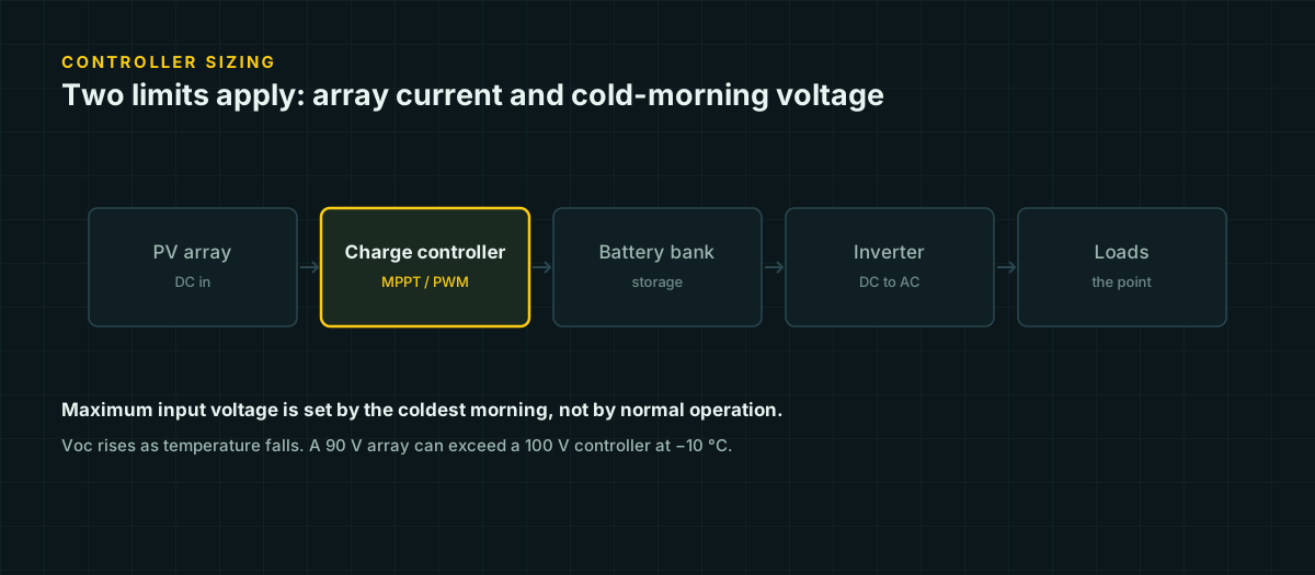
The tradeoff isn’t free. Series wiring raises the array’s operating and open-circuit voltage, which has to stay inside the charge controller’s input voltage rating — including the cold-weather Voc rise covered in our charge controller sizing guide. A series string that saves copper can also be a series string that overvolts the controller on a cold morning if nobody re-checks the voltage math after adding panels.
Shading behaves differently in each configuration
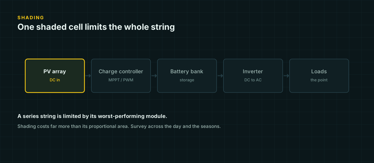
Series and parallel wiring don’t just move numbers around — they change how badly a partial shadow hurts the array, because the physics is the same worst-cell-limits-the-chain problem, just applied at a different scale.
Inside a series string, whether that string is cells inside one module or whole modules wired in series, the string’s current is capped by its weakest link. PVEducation’s explanation of mismatch effects states it plainly: “the output of the entire PV module under worst case conditions is determined by the solar cell with the lowest output.” Shade one module in a five-module series string hard enough, and you can drag the other four down toward that module’s reduced current — not just lose that one module’s contribution.
Across parallel strings, the mismatch shows up differently but the underlying cause is identical. PVEducation’s discussion of array-level mismatch describes an open circuit or shading event in one parallel-connected string leaving it “with a lower current than the remaining blocks,” which is “electrically identical to the case of one shaded solar cell in series with several good cells” — just scaled up from cells to whole strings. A weak string doesn’t just contribute less; it can pull down whatever it’s grouped with.
The practical difference is containment. With parallel strings, a shading problem confined to one string generally stays confined to that string’s contribution — the other strings keep operating independently at their own current, feeding into a combiner. With one long series string, a shading problem anywhere in the chain affects the whole chain’s output. If a site has a known, unavoidable partial-shade area — see our shading placement check for how to survey one — putting the affected modules in their own separate string (parallel to the rest, not in series with them) limits the damage to just those modules.
When parallel strings need their own fuse
Two strings in parallel is usually fine without a string-level fuse. Three or more strings usually isn’t, and the reason is back-feed, not overcurrent from the array itself.
A PV module’s short-circuit current is self-limiting — a fault within one string can’t pull more current from that string’s own panels than its Isc allows. But when three or more strings share a combiner, a fault in one string can be fed not just by that string’s own panels, but by the combined output of every other healthy string flowing backward into the fault. With only one other string, the maximum back-feed current is capped at that single string’s own current — usually within what the faulted string’s wire can absorb without protection. With two or more other strings feeding a fault, the combined back-feed can exceed what the faulted string’s conductor is rated to carry, which is exactly the condition overcurrent protection exists to catch.
This is why the general guidance is: two strings, protection is often skipped (though a disconnect is still worth having for service); three or more strings, each one gets its own fuse or breaker sized using the same NEC 690.8 current calculation covered in our charge controller sizing guide and in more depth on our DC fuse and breaker sizing page.
Combining series and parallel
Real arrays past a few hundred watts are rarely pure series or pure parallel — they’re series-parallel, called strings-in-parallel: several modules wired in series to reach a target string voltage, then multiple identical strings wired in parallel to reach a target total current or wattage.
Three practical rules keep a series-parallel array well-behaved:
- Keep every string identical. Same module count, same module model, same orientation and shading exposure. A parallel combination of unequal strings behaves like the mismatch case above even without any shading — the stronger string effectively fights the weaker one.
- Size the string count and length together against the controller’s voltage and current limits, not just whichever one you thought of first. A controller can be current-limited by too many parallel strings or voltage-limited by too long a series string, and only checking one leaves the other unchecked.
- Fuse every string once you’re at three or more, not just the ones that look risky. Back-feed capability depends on how many other strings exist, not on which specific string might fail.
Putting it together: a six-panel example
Suppose six of the illustrative 100 W modules (Vmp = 18 V, Imp = 5.56 A, Voc = 22 V, Isc = 6.0 A) need to be arranged into a 600 W array, 30 feet from the controller on 10 AWG copper. Two layouts deliver the identical 600 W; they are not equivalent once you look past the wattage.
Option A — three modules in series, two strings in parallel (3S2P). Each string: Vmp = 54 V, Voc = 66 V, Imp = 5.56 A. Two strings combined: array current = 11.12 A.
V_drop = 2 × 30 ft × 11.12 A × 0.00121 Ω/ft = 0.807 V
drop %  = 0.807 / 54 × 100 = 1.5%
690.8 current sizing: 6.0 A × 1.25 × 2 strings = 15 A, then × 1.25 = 18.75 A for the conductor/OCPD. Two strings — fusing is often skippable, though a disconnect remains worthwhile for servicing.
Option B — two modules in series, three strings in parallel (2S3P). Each string: Vmp = 36 V, Voc = 44 V, Imp = 5.56 A. Three strings combined: array current = 16.68 A.
V_drop = 2 × 30 ft × 16.68 A × 0.00121 Ω/ft = 1.211 V
drop %  = 1.211 / 36 × 100 = 3.4%
690.8 current sizing: 6.0 A × 1.25 × 3 strings = 22.5 A, then × 1.25 = 28.1 A for the conductor/OCPD. Three strings — each one now needs its own overcurrent device, per the back-feed reasoning above.
Same 600 W, same wire, same distance. Option A more than halves the percentage voltage drop and skips string fusing, at the cost of a higher array voltage the controller has to accommodate — including its cold-Voc figure. Option B keeps the array voltage lower and closer to a smaller, cheaper controller’s input range, at the cost of more copper loss and mandatory string-level fusing. Neither option is wrong; they’re different points on the same tradeoff, and the six-panel count is small enough that the difference is still modest — it gets much larger as array size grows.
Choosing
| Priority | Lean toward |
|---|---|
| Minimizing wire cost and voltage drop on a long run | Series (higher voltage, lower current) |
| Staying within a fixed low controller voltage rating | Parallel (lower voltage, higher current) |
| Containing a known partial-shade problem to a few modules | Separate parallel strings, shaded modules isolated together |
| A single unshaded panel or two, short run | Either; the difference is small at this scale |
| Three or more strings feeding one combiner | Parallel, with individual string fusing |
The right choice is rarely “always series” or “always parallel” — it’s whichever combination keeps the array’s voltage inside the controller’s window, keeps current-driven wire cost reasonable, and keeps a shading problem from spreading further than the modules that are actually shaded.
Sources and further reading
Figures on this page are traceable to the published documents below. Where a standard is referenced, check the edition your local jurisdiction has adopted before relying on it.
- Mismatch EffectsPVEducation.orgSource for the series-string worst-cell principle applied here to whole modules in series.
- Mismatch Effects in ArraysPVEducation.orgSource for parallel-string mismatch and blocking-diode/back-feed behavior between strings.
- How to Calculate Wire Size and Amps: NEC 690.8(B)Mayfield RenewablesSource for the NEC 690.8 current-sizing factors referenced in the fusing section.