A Practical Starter Plan for a Shed Solar System
A complete shed solar system derived step by step: load table, battery, array, controller, inverter, wire gauge, and fuse sizing, with every number worked on the page.
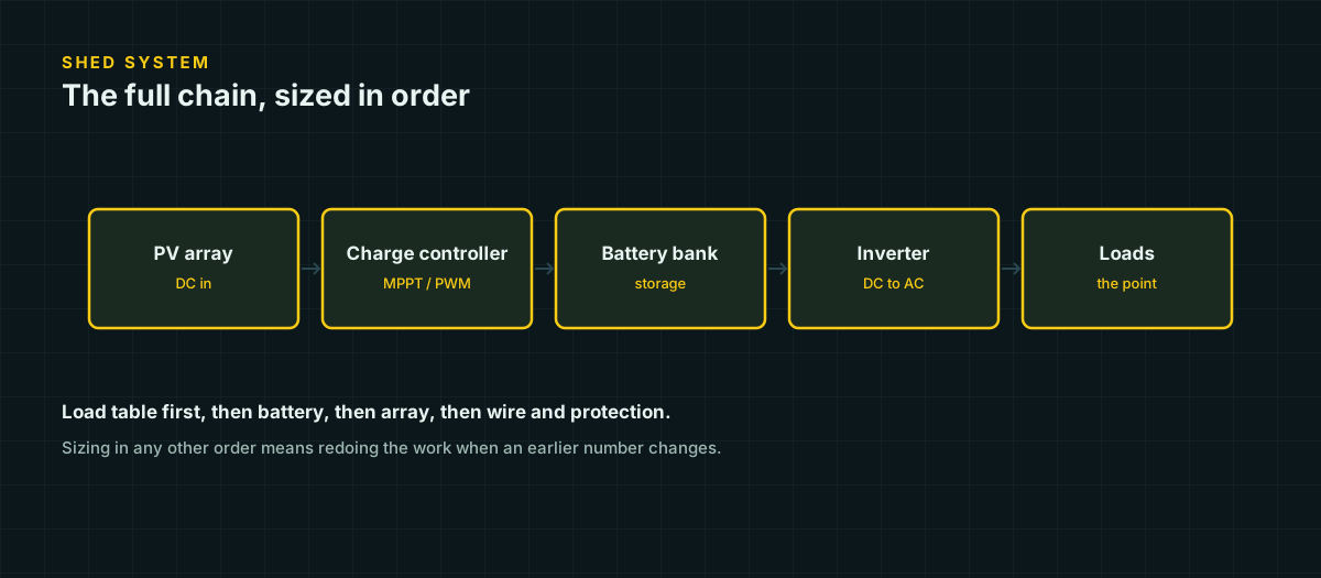
Building solar for a shed looks simple until the shopping cart fills with mismatched parts. A panel, a battery, a controller, an inverter, some wire, and a fuse block are not automatically a system — they are a system only if each part was sized from the one before it. This guide works a complete example end to end: load table, battery, array, controller, inverter, wire, and overcurrent protection, with every number derived on the page rather than asserted.
This is a small off-grid build for lighting, networking gear, occasional laptop charging, and a cordless tool charger — not a grid-tie guide. If the project connects to a home panel, touches utility power, involves roof structural work, or scales up to a large battery bank, that is licensed-electrician and permit territory; bring one in.
Start with the load
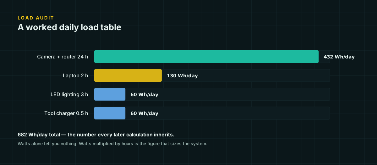
Every number below traces back to a load table. Building one properly — watts, hours, duty cycle, and the difference between nameplate and measured draw — is its own subject, covered in detail in the load audit guide. Here is the shed’s table, using measured rather than nameplate watts:
| Device | Measured watts | Hours/day | Wh/day |
|---|---|---|---|
| LED shop lights | 30 W | 3 h | 90 |
| Router + camera | 15 W | 24 h | 360 |
| Laptop charging | 45 W | 1.5 h | 67.5 |
| Cordless tool charger | 55 W | 1 h | 55 |
| Total | 572.5 Wh/day |
Applying a single 20 percent design buffer — not three stacked ones, for the reasons covered in the load audit guide — gives the design target:
572.5 Wh/day × 1.20 = 687 Wh/dayAlso note the worst-case simultaneous draw: if the tool charger, laptop charger, and lights all run at once, that’s 30 + 15 + 45 + 55 = 145 W. That figure sizes the inverter later; it plays no role in battery or array sizing.
Turn watt-hours into a battery
Battery capacity has to cover the daily design load and however many cloudy days you want to survive without recharge, divided by how much of the battery you’re willing to use:
battery Wh = (Wh/day × days of autonomy) / usable DoD fractionThis example assumes LiFePO4. Battle Born’s 100 Ah unit is rated for 100 percent usable depth of discharge, but designing to that ceiling leaves nothing for BMS low-voltage cutoff margin or a few years of capacity fade. Using 80 percent DoD as the design assumption, with 1 day of autonomy:
687 Wh × 1 / 0.8 = 858.75 WhA 12 V 100 Ah LiFePO4 battery is 1,200 Wh nominal (12 V × 100 Ah). At 80 percent DoD that’s 960 Wh usable — comfortably above the 858.75 Wh requirement, with headroom for a slightly worse month or an added device. If the shed’s 24-hour networking load is more critical than the rest, two days of autonomy roughly doubles the battery-Wh requirement and is worth pricing out separately rather than defaulted into.
Turn watt-hours into an array
Array sizing needs a peak sun hours (PSH) figure for the actual site, tilt, and azimuth — not a rule-of-thumb regional average. We don’t publish a city-by-city PSH table on this site because we could not verify one against NREL’s primary data; instead, run PVWatts with your address, tilt, and azimuth and read off the design month’s average daily sun hours.
Suppose that comes back at 4 peak sun hours for the design month. Array wattage also needs a system-loss factor: soiling, wiring, mismatch, and temperature losses are real and multiplicative rather than additive. A commonly used planning factor for a simple fixed-tilt DIY array is around 0.75 (a 25 percent combined derate) — this is a planning convention, not a code figure, and you should widen it if the site is dusty, shaded part of the day, or runs hot.
array W = daily target Wh / PSH / system efficiency
687 Wh / 4 h / 0.75 = 229 W minimum
229 W is the floor, not the target. Standard panel sizes make 300 W (three 100 W modules) a natural next step up, and the margin is worth having — a slightly oversized array recovers faster from a run of cloudy days and reduces how often the battery cycles deep.
Match a charge controller to the array
A common controller-sizing convention (again, not a code rule) is array wattage divided by battery voltage, times 1.25 for margin against cold-weather voltage rise and edge-of-cloud irradiance spikes:
300 W / 12 V × 1.25 = 31.25 AThe next standard MPPT controller size above 31.25 A is 40 A.
Watch the array’s open-circuit voltage in cold weather if you ever move to a series-string design. Module Voc rises as temperature falls, following:
Voc(cold) = Voc(STC) × [1 + (T_cell − 25°C) × (tempco / 100)]For a 100 W module with Voc(STC) around 22.3 V and a typical crystalline-silicon Voc temperature coefficient near −0.29%/°C, a cold morning at −10 °C cell temperature gives Voc ≈ 22.3 × [1 + (−35) × (−0.0029)] ≈ 24.6 V. Three 100 W modules wired in parallel — as in this build — each stay at that same ~24.6 V regardless of how many are paralleled, well inside any 12 V-class MPPT controller’s input rating. The number only becomes dangerous once you wire multiple modules in series on a 24 V or 48 V system, where the string Voc multiplies and can approach the controller’s maximum input voltage on a cold, sunny morning — a case worth double-checking explicitly rather than assuming it away.
Decide on an inverter, and size its wiring
Not every load needs an inverter. In this build, the lights and the router/camera can run on DC directly from the battery bus through a simple 12 V distribution block, avoiding conversion losses entirely. Only the laptop charger and tool charger need AC, and their combined continuous draw is 45 + 55 = 100 W — but a comfortable worst case, accounting for both running at once plus headroom, is closer to 250 W. A 300 W continuous / 600 W surge pure sine inverter covers that with margin, without the higher idle draw and heavier wiring a 2000 W unit would demand for no reason.
DC input current at the battery, 250 W AC load, 88 percent inverter efficiency, 12 V nominal:
250 W / 0.88 / 12 V = 23.67 ADesign the conductor for continuous duty using the same 1.25× multiplier that governs continuous loads generally (see DC fuse and breaker sizing for where this comes from):
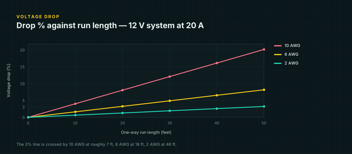
23.67 A × 1.25 = 29.6 A design currentBy NEC 75 °C ampacity, 10 AWG is rated 35 A — enough on paper, with about 18 percent headroom. Most builders choose 8 AWG or larger for a battery-to-inverter run despite that, because inverter surge current during motor or charger startup briefly exceeds the steady-state figure, and heavier cable keeps voltage drop lower under that transient. Checking drop for an inverter mounted 3 feet from the battery, on 8 AWG (0.764 Ω/1000 ft):
V_drop = 2 × 3 ft × 24 A × 0.000764 Ω/ft = 0.11 V
drop % = 0.11 / 12 × 100 = 0.9%
Comfortably under the 3 percent target from the voltage drop tables. Move that same inverter 15 feet away instead of 3, and the drop scales linearly with length — five times the distance is five times the drop, or about 4.6 percent, already past the limit on the same wire. This is the entire argument for mounting the inverter next to the battery rather than across the shed: the wire size that works at arm’s length can fail at across-the-room distances on the exact same circuit.
Protect every circuit
Every current-carrying conductor in this build needs overcurrent protection sized to the wire it feeds, placed as close to the source as practical — the full reasoning is in DC fuse and breaker sizing. Three circuits, three calculations:
PV source circuit. Suppose the array uses three 100 W modules in parallel, each rated 5.95 A short-circuit current (Isc). NEC 690.8 applies 125 percent twice:
690.8(A): 5.95 A × 1.25 × 3 strings = 22.3 A
690.8(B): 22.3 A × 1.25            = 27.9 A
Conductor and OCPD both need to clear 27.9 A. 10 AWG at 35 A (75 °C, NEC) covers it, and the next standard fuse or breaker size above 27.9 A is 30 A.
Controller to battery. Following the same vendor-guidance convention used in the overcurrent-protection reference — fuse at 1.25× the controller’s rated output — a 40 A controller gets a 50 A fuse. Size this conductor for at least 50 A of ampacity too; 8 AWG (50 A at 75 °C) is the bare minimum, and 6 AWG (65 A) is the more comfortable choice for a run of any real length.
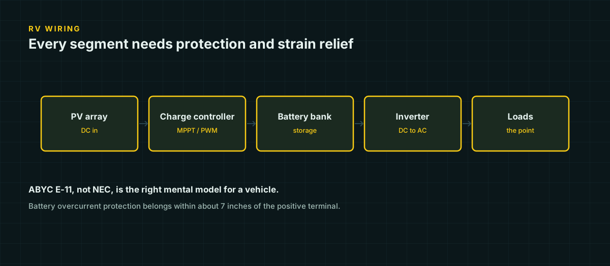
Battery to inverter. The design current here was 29.6 A, with a conductor chosen to be rated well above that. A fuse in the 30–40 A range covers the load with margin below the conductor’s ampacity while riding through inverter startup. Because this is a LiFePO4 bank, that fuse should be Class T — its interrupting rating is built for lithium’s much higher prospective fault current, where an ANL fuse sized for lead-acid can weld shut instead of opening. Place it within a few inches of the battery’s positive terminal.
The parts shape, not a shopping list
This is a shape a system like the one worked above takes — not prices, and not a substitute for your own numbers:
- ~300 W of solar panels (three 100 W modules, wired in parallel for this 12 V design)
- 40 A MPPT charge controller
- 12 V 100 Ah LiFePO4 battery with a BMS that publishes its low-temperature charge cutoff
- 300 W continuous / 600 W surge pure sine inverter, only if AC loads are actually present
- 10 AWG minimum (8 AWG or larger recommended) for the PV and inverter circuits; 6–8 AWG for controller-to-battery
- 30 A PV source-circuit fuse or breaker, 50 A controller-to-battery fuse, Class T fuse at the battery-to-inverter circuit
- Battery disconnect, PV disconnect, lugs matched to conductor stranding, and labeled shutdown order
Your loads, wire lengths, climate, and mounting will change every number in this list. Rebuild the calculation for your own site rather than shopping from this one.
Where a non-electrician should stop
Everything above is planning arithmetic from published formulas and manufacturer guidance, not a substitute for the instructions that came with your specific equipment or for local code. A DIY builder can reasonably plan, wire, and commission a system like this one at the current levels involved here — tens of amps, a single small battery, low voltage throughout. The line moves once the system connects to a structure’s existing electrical panel, involves roof penetrations or structural mounting, scales to a bank large enough to deliver serious fault current, or touches anything resembling utility interconnection. At that point the right move is a licensed electrician’s review before anything gets energized, not a bigger fuse.
Sources and further reading
Figures on this page are traceable to the published documents below. Where a standard is referenced, check the edition your local jurisdiction has adopted before relying on it.
- NEC 690.8 — Circuit Sizing and Current for PV SystemsNFPA 70, explained by Mayfield Renewables
- NEC Table 310.16 — Allowable Ampacities of Insulated ConductorsNFPA 70, republished by wiresizes.comNFPA 70 is copyrighted; values transcribed from a third-party reproduction cross-checked for internal consistency.
- NEC Chapter 9, Table 8 — Conductor Properties (DC resistance, uncoated copper)NFPA 70, republished by buildmyowncabin.com
- 12.8 & 25.6 Volt Lithium Iron Phosphate Batteries Smart — datasheetVictron EnergySource for LiFePO4 round-trip efficiency and charge-acceptance figures.
- 100Ah 12V Smart LiFePO4 Deep Cycle Battery — specificationsBattle Born BatteriesSource for 100% usable depth of discharge on this reference product.
- How to fuse your solar systemRenogyManufacturer guidance, not a code requirement — source for the 1.25x controller-to-battery fuse convention.
- Matching Victron Energy solar modules to the new MPPT charge regulatorsVictron EnergySource for the cold-weather Voc rise formula and typical module temperature coefficients.