RV Solar Wiring Checklist: Fuses, Disconnects, and Cable Routes
A sequential RV solar wiring checklist built on ABYC E-11: engine-space derating, the 7-inch fuse rule, disconnect placement, and chafe protection.
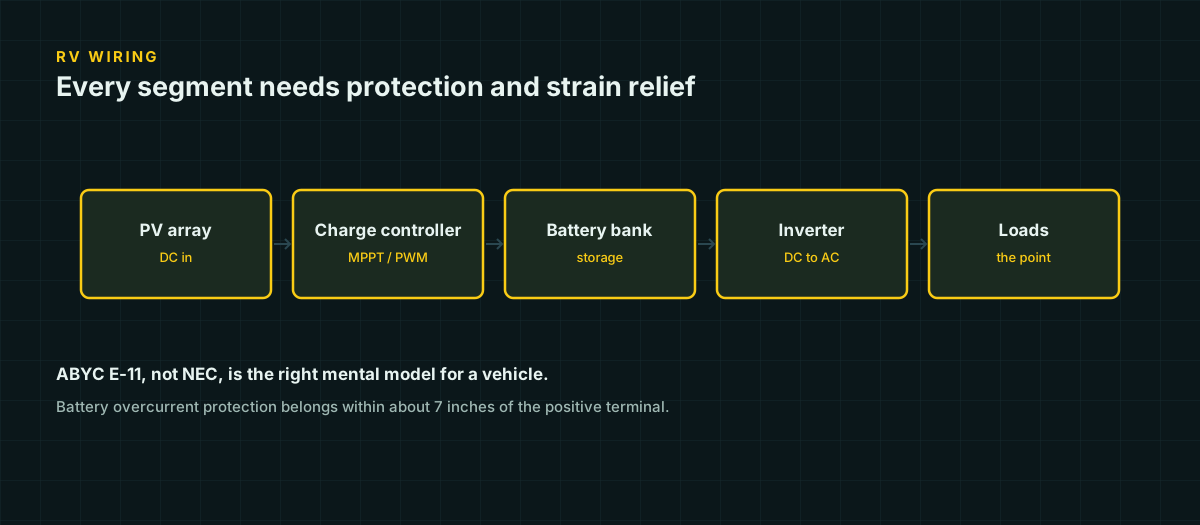
An RV is not a house with wheels, and wiring it like one is a common source of failures that look mysterious later. The vibration is constant, the ambient temperature near an engine or generator bay is nothing like a 30 °C wall cavity, and every drilled hole in a steel or aluminum chassis is a potential edge waiting to saw through insulation on the next thousand miles of washboard road. The standard that actually describes this environment is ABYC E-11, not the NEC — and treating your build like a stationary house install is where a lot of “it worked in the driveway” systems start failing on the road.
This is a sequential checklist for a small RV solar system: panels, charge controller, battery, DC distribution, and an optional inverter. Work through it roughly in order — current path first, protection second, physical routing last — because each step assumes the ones before it are settled.
Why ABYC E-11, not NEC, is the mental model
NEC Table 310.16 assumes a conductor in a raceway or cable, in a 30 °C ambient, with at most three current-carrying conductors nearby. That describes wire inside a wall. It does not describe wire zip-tied along a chassis rail six inches from a generator.
ABYC E-11 assumes single conductors in free air, and it further splits its ampacity table into conductors outside engine spaces and conductors inside them, because an engine compartment starts hot before any current flows through the wire at all. Full ampacity tables and the temperature/bundling derates that apply to each standard are in the DC wire ampacity reference; the short version that matters for a vehicle build is this: use ABYC’s numbers, and specifically its engine-space column for anything routed near an engine, generator, or exhaust path.
The engine-space penalty is not a rounding error. At 75 °C, 8 AWG carries 65 A outside an engine space and only 48.8 A inside one — a 25% reduction from location alone. In a van or RV, “engine space” should be read generously: anywhere that gets hot and stays hot while the vehicle runs, not just the compartment with the engine in it.
Step 1 — Map the current path and size for where it actually runs
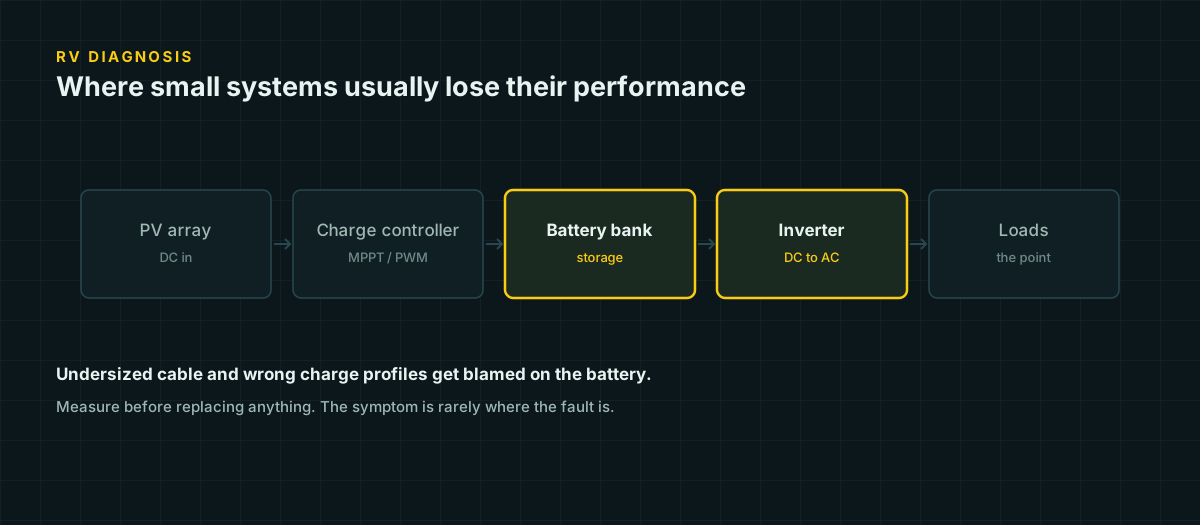
Before buying wire, trace the full path current will follow: panel → controller → battery → fuse block or inverter → load → return conductor. Note which segments pass through or near hot spaces, which are exposed to vibration, and the one-way distance of each segment — you’ll need the round-trip length for voltage drop, covered in the voltage drop guide.
Here is that process worked through on a realistic RV circuit: a 40 A DC-DC charger pulling from the alternator, run 8 feet one-way from the engine bay through the firewall to the house battery, routed for its full length through what should be treated as engine space.
Ampacity. At 75 °C, ABYC’s inside-engine-space column gives 8 AWG a rating of 48.8 A — above the 40 A load, so ampacity alone would allow 8 AWG.
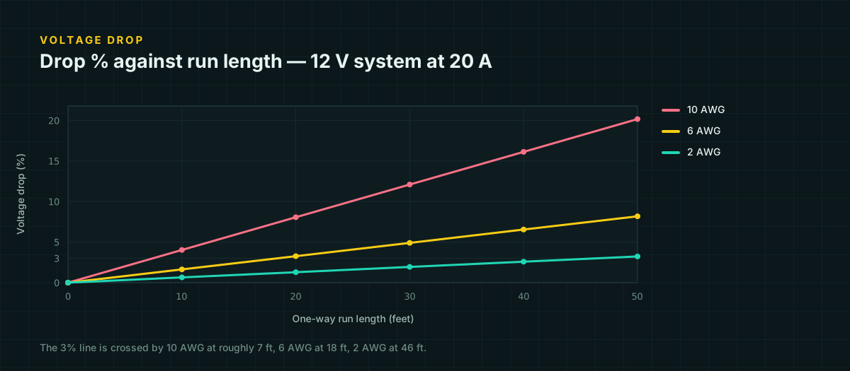
Voltage drop. Using 8 AWG’s resistance of 0.000764 Ω/ft:
V_drop = 2 × 8 ft × 40 A × 0.000764 Ω/ft = 0.489 V
drop % = 0.489 / 12 × 100 = 4.1%
That exceeds ABYC’s 3% limit for a critical DC circuit. Step up to 6 AWG, at 0.000491 Ω/ft:
V_drop = 2 × 8 × 40 × 0.000491 = 0.314 V
drop % = 0.314 / 12 × 100 = 2.6%
6 AWG clears both tests: ampacity at 71.3 A inside engine space (far above 40 A) and drop at 2.6%. Ampacity said 8 AWG was enough; drop said otherwise, on a run only 8 feet long. That gap is exactly why both checks belong in every segment of the map, not just the long ones.
Step 2 — Fuse placement: the 7-inch rule and beyond
The battery is the only component capable of delivering a genuinely dangerous fault current, so its output gets protected first and closest. ABYC E-11 specifies overcurrent protection within 7 inches (18 cm) of the battery positive terminal. That short stub of unprotected cable between the post and the fuse holder is the one piece of wire in the system a fuse cannot protect — keep it as short as physically possible and treat it with the same chafe protection as the rest of the run.
Beyond the battery, protection belongs at each of these points, sized to the wire it protects rather than to the device at the far end:
- Between the charge controller and the battery.
- Between the PV array and the controller, once more than two strings are wired in parallel and can back-feed a fault in one string.
- Between the battery and the inverter — usually the highest-current circuit in the system and the one most often left unfused because the cable is short.
- On the DC-DC charger and alternator-fed circuit, both at the battery end and, per most charger manufacturer instructions, near the alternator/starter-battery end as well.
The full sizing logic — the 125% continuous-load rule, interrupting rating, and why lithium banks need a higher-AIC fuse than lead-acid — is in the DC overcurrent protection reference; this checklist only covers placement.
Step 3 — Disconnects: service versus storage
Two different disconnects solve two different problems, and conflating them is a common gap.
| Disconnect | Purpose | Typical location |
|---|---|---|
| Service disconnect | Isolate a section of the system for inspection, a blown fuse, or adding a device, without killing the whole system | Near the component being serviced — a PV disconnect near the controller, a battery disconnect near the battery |
| Storage / master disconnect | Fully isolate the battery from every load during long-term storage, to stop parasitic draw from a clock, alarm, or standby-mode inverter from slowly draining the bank | A single accessible switch or lever at the battery, reachable without opening interior panels |
Both need to be reachable without tools and without disassembling cabinetry. A disconnect buried behind a mounted inverter or wedged under a bed platform gets used once, at install, and never again — which defeats the purpose of having one.
Step 4 — Vibration and chafe protection along the route
A stationary shed installation never has to survive washboard gravel at 55 mph. An RV does, for the life of the system. Two failure modes are specific to this environment:
Insulation abrasion. A cable resting against a sharp metal edge — a chassis rail, a drilled hole’s burr, a cabinet corner — will wear through its jacket under sustained vibration, sometimes over months rather than a single trip. Route cable away from sharp edges wherever possible, and where it can’t be avoided, add a section of split loom or heat-shrink abrasion sleeve at the contact point.
Connector and terminal fatigue. Vibration works loose what torque alone holds together. Lock washers, thread-locking compound on accessible fasteners, and periodic re-torque checks after the first few hundred miles catch this before it becomes an intermittent connection — which is a harder fault to diagnose than one that fails outright.
Step 5 — Grommets and bulkhead pass-throughs
Every place a cable crosses a metal panel — a firewall, a battery box wall, a cabinet floor — needs a grommet or a purpose-built bulkhead fitting, not a bare hole. The mechanism is straightforward: a drilled hole in sheet metal has a sharp, sometimes burred edge, and that edge is exactly where the vibration described in Step 4 concentrates its damage. A snap-in rubber grommet or a sealed bulkhead connector spreads the cable’s bend over a rounded surface instead of a knife edge, and doubles as a barrier against water tracking along the cable into a compartment it shouldn’t reach.
Size the grommet to the cable’s outer diameter, not its conductor gauge — a grommet that’s too large lets the cable move inside it and wear anyway.
Step 6 — Routing away from heat and fuel lines
Keep DC wiring clear of exhaust runs, engine heat, and any fuel line, propane line, or fuel tank, for two independent reasons.
Heat ages insulation. A cable routed against a hot surface runs at a higher continuous temperature than its ampacity table assumed, which both reduces its safe current-carrying capacity and shortens its working life.
The fuel-line concern is about what happens if something does go wrong. DC current does not cross zero volts the way AC does — an AC arc gets a natural extinguishing opportunity 100 to 120 times a second as the current reverses; a DC arc has no such moment and, once struck at a loose connection or a chafed-through conductor, can sustain itself indefinitely, generating heat and sparks at the fault point. That is a mechanism you do not want anywhere near a fuel vapor source. Routing DC wiring with real physical separation from fuel and propane lines is not a cosmetic choice.
Step 7 — Strain relief
Every termination — a lug, a fuse holder, a busbar — should have the cable supported so that flexing and vibration are absorbed by a clamp or cable tie a few inches back from the joint, not by the joint itself. Without strain relief, the constant micro-flexing of highway travel concentrates cyclic stress at the exact point where strands meet the lug barrel, which is also the point with the least ability to flex. Terminals fail there first, and they fail slowly, as a gradually rising resistance rather than a clean break — which makes strain relief one of the cheapest and least visible reliability investments in the whole build.
Step 8 — The chassis-ground question
Automotive and RV chassis wiring has a long history of using the vehicle’s metal frame as the return path for accessory circuits — one wire out to a light or a switch, the frame itself carries the current back to the battery negative. That works for headlights and marker lights because those circuits were engineered around it from the factory, with defined ground straps and known current levels.
A house-power solar system should not rely on the chassis as a return conductor, and this is common installer and DIY practice rather than a codified rule the way the 7-inch fuse placement is. Run a genuine insulated negative conductor from every load back to a common DC negative busbar, sized and protected the same as the positive side. The chassis path has no defined resistance, no fuse of its own, and depends on a body-to-frame ground strap that can corrode or loosen without any obvious symptom until a fault occurs — at which point a resistive, unfused metal path is exactly the wrong thing to have carrying inverter or charger current. Isolated two-wire distribution also avoids ground loops that show up as electrical noise in sensitive electronics when a chassis return and a proper negative bus share current unpredictably.
Before you energize
Work through this in order, after the physical build is complete and before power is connected for the first time:
- Confirm battery polarity at every connection point before anything is torqued down.
- Confirm the battery fuse is installed within 7 inches of the terminal, in an accessible holder.
- Confirm every segment identified in Step 1 has been checked against both ampacity and voltage drop, not just one.
- Confirm the PV disconnect, battery disconnect, and storage disconnect are all reachable without removing panels or furniture.
- Confirm every pass-through has a grommet or bulkhead fitting, not a bare drilled hole.
- Confirm no run passes within a few inches of an exhaust path, engine heat, or a fuel/propane line without abrasion and heat protection.
- Confirm strain relief exists within a few inches of every lug, fuse holder, and busbar connection.
- Confirm the DC negative distribution is a genuine two-wire system back to a common busbar, not a tap off the chassis.
- With the system live and under a real load, measure voltage at both ends of at least one long run with a multimeter and compare it to the calculated prediction — see how to measure drop on an energized system.
A system that passes all nine checks is not guaranteed to be perfect, but it has been checked against the specific ways RV wiring fails — vibration, chafe, heat, and the fact that a vehicle is not a wall. That is a meaningfully different, and more relevant, bar than “it matches a house wiring diagram.”
Sources and further reading
Figures on this page are traceable to the published documents below. Where a standard is referenced, check the edition your local jurisdiction has adopted before relying on it.
- ABYC E-11 Table 6A — single conductors not bundled/sheathed/in conduit (marine and RV)American Boat and Yacht Council, reproduced with permission by BoatHowToPDF is marked 'Courtesy ABYC, E-11, Table 6A. Used with permission.' Source for the engine-space ampacity figures.
- Battery bank overcurrent protection and fuse placementMarineHowToSource for the ABYC 7-inch battery-fuse placement guidance.
- NEC Chapter 9, Table 8 — Conductor Properties (DC resistance, uncoated copper)NFPA 70, republished by buildmyowncabin.comResistance values used in the worked drop calculation.