PV Wire, MC4 Connectors, and Battery Cable: Choosing the Right Conductor
How PV wire, USE-2, THHN/THWN-2, welding cable, and marine battery cable differ, and why MC4 connectors from different brands are a documented fire hazard.
A wire is not just a gauge number. Two conductors of identical AWG can be rated for completely different environments, terminate with completely different hardware, and fail in completely different ways — one gracefully, one by catching fire. Choosing the type of conductor and connector is a separate decision from sizing it, and it is the one DIY guides skip most often.
This covers where PV wire, USE-2, THHN/THWN-2, welding cable, and marine battery cable each belong, the MC4 connector compatibility problem that catches even careful builders, and why the crimp matters as much as the cable.
PV wire, USE-2, and THHN/THWN-2: what the ratings mean
These three show up constantly in solar builds and get treated as interchangeable. They are not.
PV wire, certified to UL 4703, is the purpose-built conductor for exposed, outdoor photovoltaic wiring. It shares a 90 °C wet temperature rating with USE-2, but it is additionally tested for sunlight exposure under UL 4703’s accelerated UV protocol, and manufacturers quote a higher short-term dry/overload rating on top of that — though the exact ceiling varies by source (some manufacturer literature says 150 °C, other technical pages say 120 °C short-term), so check the specific product’s datasheet rather than assuming the higher number. PV wire is also commonly available in 600 V, 1000 V, and 2000 V variants, ahead of where USE-2 and THHN stop at 600 V.
USE-2 is an older underground-service-entrance conductor type that solar adopted before UL 4703 existed as a dedicated PV standard. It shares the 90 °C wet rating and is genuinely sunlight-resistant, but it is not certified against UL 4703’s sunlight test and carries thinner insulation for the same gauge than PV wire typically does. It remains common and legal in a lot of installations, but it is being displaced by PV wire, especially on transformerless (ungrounded) inverter systems, which commonly require the higher-rated PV-wire listing rather than accepting USE-2 as a substitute.
THHN/THWN-2 is ordinary building wire, dual-rated for dry (THHN, 90 °C) and wet (THWN-2, typically 75 °C in older ratings, 90 °C in newer ones) locations. It is inexpensive, widely stocked, and completely wrong for a run that sees direct sun. It carries no certified sunlight or UV rating at all, and unlike PV wire or USE-2 it will visibly degrade — insulation cracking, embrittlement — within a few years of continuous outdoor exposure. Its correct place in a solar build is inside conduit, out of direct sunlight: home runs from a combiner box to a charge controller, or any DC wiring routed through a wall or raceway where sun never touches it.
The practical rule: if a conductor will ever see direct sunlight — array wiring, exposed home runs across a roof, anything outdoors and unprotected — it needs to be PV wire or USE-2. Once it’s inside conduit, indoors, or otherwise shielded from UV, THHN/THWN-2 is a legitimate and cheaper choice, provided its ampacity and temperature rating still clear the circuit’s requirements. See the DC wire ampacity reference for those numbers.
Welding cable and marine battery cable: the flexible-conductor world
Battery interconnects and inverter cables live in a different world from the array wiring above: short, thick, flexible, high-current, low-voltage.
Welding cable is the default DIY choice for these runs because it is cheap, extremely flexible from its very fine stranding, and sold everywhere in large gauges. What it is not, in most cases, is a listed vehicle, marine, or building-wire product. A spool of welding cable typically carries no SAE, UL, or ABYC listing at all unless the specific product explicitly says so — it is class-K-style flexible cable intended for arc-welding leads, and its jacket is not guaranteed to be rated for outdoor sun, marine wet locations, or oil exposure the way a listed product is. That does not make it unusable, but it means the buyer, not a standard, is responsible for confirming what the insulation actually tolerates.
SAE J1127 battery cable is the automotive-world alternative: a real standard, rated to a maximum of 60 VDC, typically stocked from 6 AWG and up for starter and chassis-ground leads, with insulation commonly rated in the 80–105 °C range depending on the manufacturer’s specific product. It is a genuine listed product, not just a description on a listing page.
Marine tinned battery cable, built to UL 1426, is the option built for corrosion. Independent retailer specifications for UL 1426 cable consistently show a 600 V rating, 105 °C dry / 75 °C wet temperature rating, and tinned Type III stranding — copper strands individually coated in tin before being stranded together, not just tinned at the cut end. UL 1426 is the standard the US Coast Guard references for boat wiring, and it is a reasonable default choice for any battery interconnect that will see damp air, condensation, or proximity to lead-acid off-gassing, not just literal boats.
For a dry, indoor, permanent installation, plain welding cable from a reputable spool — confirmed 100% copper, not copper-clad aluminum — is a defensible and economical choice. For anything in a vehicle, a van, an outdoor enclosure, or near moisture of any kind, the marginal cost of a listed marine or automotive product is worth paying. The stranding, tinning, and copper-purity issues that make the difference are covered in full in the AWG to mm² conversion and copper-clad aluminum guide — this article won’t repeat that table, but the buying traps described there apply directly to every cable type on this page.
MC4 connectors and the cross-brand hazard
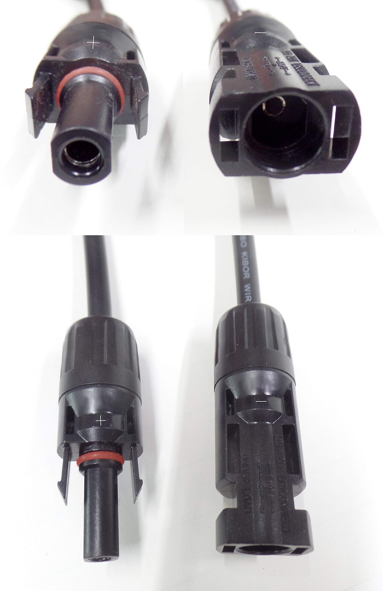
MC4-style connectors are the near-universal snap-together plug used on panel leads and array home runs. Nearly every manufacturer’s connector looks the same: same size, same locking tab, same general shape. That visual similarity is the trap.
Connectors from different manufacturers are not listed to mate with each other, even when they appear to click together and lock. The 2020 NEC, at 690.33(C), requires PV connectors to be either from the same manufacturer or explicitly listed as intermatable by an accredited testing lab; UL 6703 sets the same expectation for the connector’s listing itself, and IEC 62548 imposes an equivalent same-origin requirement for installations following international design rules. None of these documents treat “it clicked and looks tight” as evidence of a safe connection.
The mechanism matters here, not just the rule. A cross-brand pairing can have subtly different pin dimensions, contact spring pressure, or gasket geometry than a matched pair, even though both individually meet spec against their own manufacturer’s connector. The result is a mated pair with higher contact resistance than either connector was tested for — a resistive heat source sealed inside a weatherproof housing that is also, by design, good at retaining heat rather than shedding it. That heat builds with every thermal cycle the connection goes through, and a sealed, UV-resistant housing melting from the inside is a documented cause of rooftop PV fires.
The practical fix costs nothing: buy connectors and cable-mounted plugs from a single manufacturer for a given run, and if a panel or extension cable arrives with a connector from a different brand than the rest of the system, replace it rather than mate it. Reputable connector kits are inexpensive relative to the rest of an array; this is not the place to improvise.
Crimping versus the hardware-store crimp
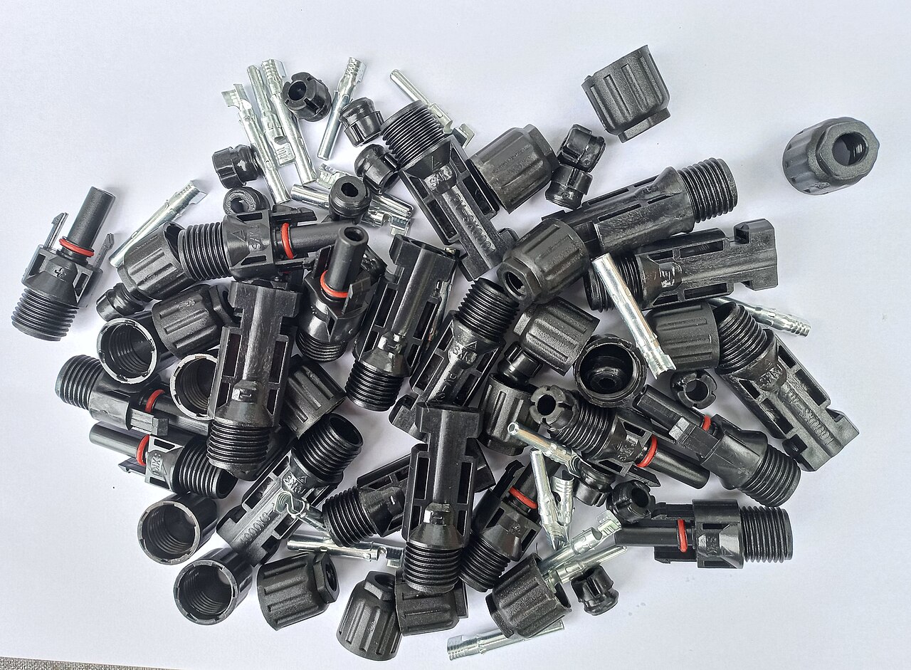
A crimp connection works by cold-deforming metal until the lug barrel and the wire strands are compressed into one another firmly enough that no meaningful air gap or void remains — effectively a mechanical weld. A correctly sized hydraulic or ratcheting crimper, with a die matched to the lug and wire gauge, compresses the entire circumference of the barrel evenly, driving every strand into contact.
A generic hardware-store crimper, of the pliers-with-a-notch type sold for automotive spade terminals, does something different: it squeezes a single indent into one side of the barrel. That indent contacts some of the strands underneath it and leaves others barely touched, especially on a fine-stranded conductor. Current then concentrates through the strands that are actually making good contact, those strands run hotter than the rest of the bundle, and the joint’s real capacity is lower than the wire’s rated ampacity would suggest — even though the crimp looks structurally fine from the outside and holds under a tug test.
For anything carrying more than a few amps at battery voltage, use a crimper rated for the lug and wire size in question — typically a hex or hydraulic crimper for anything 8 AWG and larger — not a general-purpose terminal tool.
Choosing a conductor: quick reference
| Application | Reach for | Not this | Why |
|---|---|---|---|
| Array wiring exposed to direct sun | PV wire (UL 4703) or USE-2 | THHN/THWN-2 | THHN carries no certified sunlight rating and embrittles outdoors |
| Home run inside conduit, out of the sun | THHN/THWN-2 | — | Cheaper, widely stocked, appropriate once UV exposure is eliminated |
| Battery-to-inverter or battery-to-busbar, dry indoor location | Welding cable, confirmed 100% copper | Unlabeled “battery cable” of unknown origin | Flexible and affordable, but verify copper purity and jacket rating yourself |
| Battery interconnects in a vehicle, boat, or damp enclosure | UL 1426 marine tinned cable or SAE J1127 | Bare-copper welding cable | Tinning and a real listing resist the corrosion an unlisted cable won’t |
| Panel-to-panel and array home-run connectors | Matched-brand MC4 connectors | Mixed-brand “compatible” connectors | Cross-brand pairs are not listed to mate and are a documented fire cause |
The copper-shortfall trap, worked
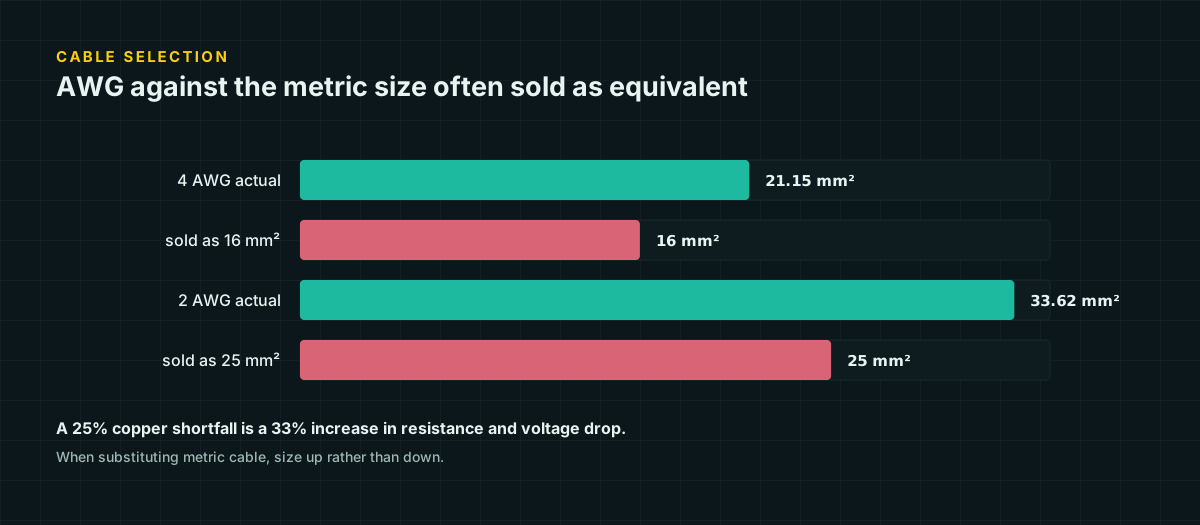
Suppose a 25 A, 12 V battery-to-inverter run is 15 feet one-way and is wired with cable sold as “8 AWG equivalent” welding cable that actually measures 6 mm² of copper — a real substitution the market makes, detailed further in the AWG to mm² reference. True 8 AWG is 8.367 mm². Resistance is inversely proportional to cross-sectional area for the same material and length, so:
R_substitute = R_8AWG × (8.367 / 6.0) = 0.000764 Ω/ft × 1.3945 ≈ 0.001065 Ω/ftCompare the drop each produces on the same run:
True 8 AWG:   V_drop = 2 × 15 × 25 × 0.000764 = 0.573 V   → 4.8% of 12 V
Substitute:   V_drop = 2 × 15 × 25 × 0.001065 = 0.799 V   → 6.7% of 12 V
Nothing about the connectors, the crimp, or the insulation rating changed. The substitution alone moved the circuit from a marginal-but-plannable 4.8% to a drop most critical-circuit guidance would reject. Buying by the label instead of the measured cross-section is not a small mistake on a high-current, low-voltage run — it’s the difference between a design that clears its target and one that doesn’t.
Sources and further reading
Figures on this page are traceable to the published documents below. Where a standard is referenced, check the edition your local jurisdiction has adopted before relying on it.
- MC4 connector — cross-manufacturer compatibility and NEC/UL/IEC requirementsWikipediaTertiary source; used for the NEC 690.33(C), UL 6703, and IEC 62548 same-manufacturer requirement, cross-checked against its own citations.
- Solar PV Wire vs USE-2 Wire: What's the Difference?KrisTech WireManufacturer technical page; source for the PV wire vs USE-2 temperature and sunlight-rating comparison.
- Comparative Analysis of UL 4703 PV Cable, RHW-2, and XHHW-2 CablesGreaterWireManufacturer technical page; source for THHN's lack of a sunlight/UV rating and PV wire's temperature range.
- SAE J1127 and J1128: Battery Cable and Primary Wire SpecificationsLectromecSource for the SAE J1127 battery-cable voltage rating and typical gauge range.
- 4 Gauge Tinned Marine Battery Cable, UL 1426WireAndCableYourWay.comRetailer specification page, not the UL standard text itself; figures cross-checked against a second independent retailer listing before use.
- AWG to mm conversion calculator and referenceRapidTablesCross-sectional area figures used in the copper-shortfall worked example.