Seven RV Solar Mistakes That Make Small Systems Feel Weak
Seven RV solar mistakes explained by mechanism, symptom, and confirming measurement — from undersized cable and wrong charge profiles to alternator charging assumptions that fail on LiFePO4.
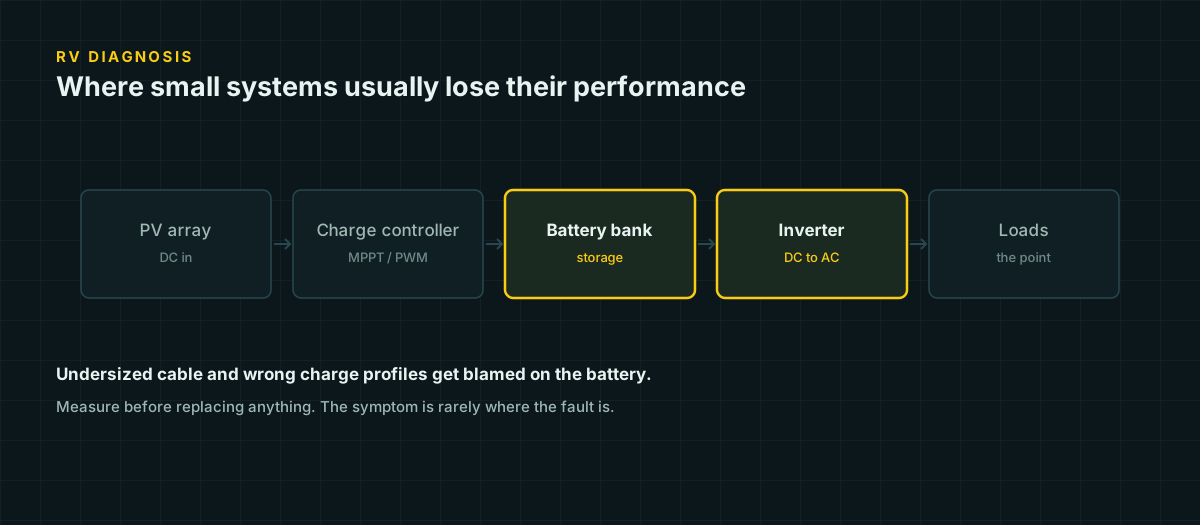
RV solar systems fail in ordinary, repeatable ways, and almost every one of them gets misdiagnosed on the first guess. The battery gets blamed for a wiring problem. The panel gets blamed for a controller setting. The alternator takes damage nobody connects to the lithium upgrade six months earlier. Each mistake below is described with what actually causes it, the symptom it produces, the measurement that confirms it, and the fix — because “add more panels” is the wrong answer to most of these, and knowing which one you have changes what you do next.
1. Undersized cable that gets blamed on the battery
The mechanism. Every meter of wire has resistance, and low-voltage DC systems push far more current through that resistance than the equivalent AC load would. A 1000 W inverter running on a 12 V battery draws over 80 A before losses — roughly sixteen times the current of the same load at 120 V AC. Voltage drop follows Ohm’s law directly: V_drop = 2 × L × I × R, where the factor of two accounts for the full round-trip path, out and back.
The symptom. The inverter shuts down under load, or shuts down intermittently, while the battery monitor claims a healthy state of charge. Lights dim when a pump or compressor kicks on. None of this looks like a wiring problem from the driver’s seat — it looks exactly like a bad or aging battery.
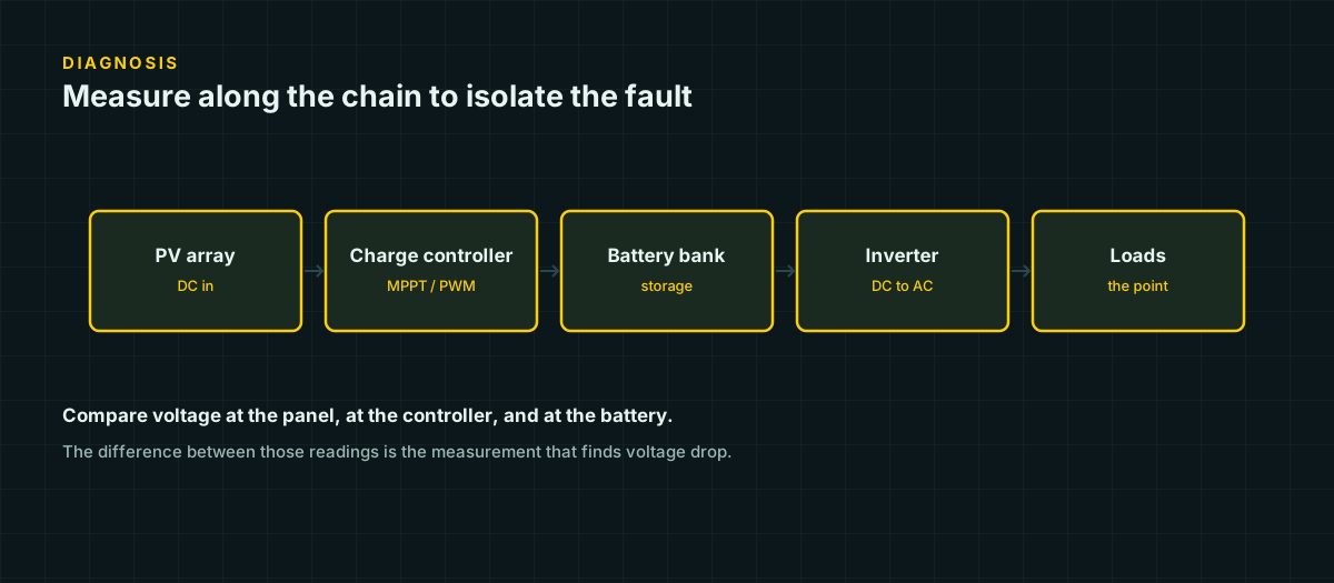
The confirming measurement. Measure battery voltage at the terminals and, simultaneously, at the load end of the cable, both under the load that triggers the symptom. A gap of more than a few tenths of a volt at 12 V is the cable, not the battery. If the battery terminal reading itself sags heavily under load while the far-end gap stays small, that points back toward the battery instead — this single comparison is what tells the two apart.
The fix. Size for ampacity first, then check voltage drop separately — ampacity is a safety limit and voltage drop is a functionality limit, and on a low-voltage RV run the drop calculation almost always demands larger wire than the ampacity table does. Our voltage drop tables give the maximum one-way run length by wire size and current for the common voltage drop targets.
2. Wrong charge profile for the battery chemistry
The mechanism. A multi-chemistry charge controller’s “battery type” setting is not a label — it sets the actual absorption and float voltages the controller targets. Those targets differ meaningfully between chemistries: AGM absorption runs roughly 14.2 to 14.9 V at 12 V nominal, gel runs lower at roughly 14.1 to 14.4 V, and LiFePO4 uses a different curve entirely, with most manufacturers specifying their own controller settings.
The symptom. A gel battery left on an AGM profile is chronically overcharged — it gasses, its electrolyte dries out, and its life shortens well below its rated cycle count. An AGM battery on a gel profile never quite reaches full. A lithium bank on either lead-acid profile can undercharge, overcharge, or trip its own battery management system depending on which direction the mismatch runs.
The confirming measurement. Check the controller’s actual absorption voltage setting in its menu against your specific battery’s datasheet. This takes two minutes and is the fastest test on this entire list.
The fix. Set the profile to match the datasheet, not the factory default. If the controller cannot be configured precisely enough for a lithium bank’s requirements, confirm with the battery manufacturer that the controller is compatible at all before relying on it for the first real charge cycle.
3. Inverter idle draw exceeding the actual load
The mechanism. An inverter that is switched on consumes power continuously to run its own internal electronics, independent of whatever load is or isn’t plugged into its output. This idle draw is small in absolute terms — often single-digit to low double-digit watts — but it runs around the clock if the inverter is left on, while the loads it serves may run for minutes at a time.
The symptom. The battery drains measurably even on days when almost nothing was deliberately run through the inverter. Overnight state of charge drops more than the known loads explain.
The confirming measurement. With every known load disconnected and the inverter switched on, clamp an ammeter on the battery cable and read the current. That number, multiplied by 24 hours, is what the inverter alone costs per day just for being awake.
The fix. Switch the inverter off when its loads are not in use, or route always-on low-power devices — routers, small chargers, monitoring displays — through a DC circuit instead of through the inverter. An inverter’s conversion loss and idle draw together can spend more energy keeping the inverter powered than the connected device itself consumes.
4. An array too small for the bank’s charge acceptance — or too small for the load
The mechanism. Every battery chemistry has a maximum rate at which it will accept charge current, expressed as a fraction of its capacity (a “C-rate”). AGM and gel are commonly rated around 0.2C — a 100 Ah battery accepting about 20 A. LiFePO4 accepts far more, commonly 0.5C continuous and up to 1C briefly. An array sized well below what the battery could accept leaves capacity on the table; an array sized to fully exploit a lithium bank’s fast charge acceptance will badly overwhelm a lead-acid bank’s much lower limit if the chemistry is ever changed later without resizing anything else.
The symptom. The battery takes far longer to reach absorption than the array’s rated wattage would suggest it should, or — in the reverse case — a controller that never seems current-limited despite a large array, because the battery itself is the bottleneck.
The confirming measurement. Compare the array’s actual measured output current at peak sun to the battery’s rated charge-acceptance current from its datasheet. If the battery’s acceptance limit is below what the array can produce, the array is not underperforming — it is producing more than the bank can use, and the controller is correctly throttling it.
The fix. Size the array to the smaller of two ceilings: the daily energy the loads require, and the battery’s charge-acceptance rate. Chasing more panel wattage past the battery’s own acceptance limit does not shorten recharge time.
5. Shading from roof furniture
The mechanism. RV roofs are crowded with vents, air conditioners, antennas, and racks, and a series-wired string of cells shares current — a shadow across even one cell can drag down the output of the entire string it belongs to, not just its own fractional share of the panel’s area.
The symptom. Output is consistently lower than the panel’s rating would suggest, especially at specific times of day when the sun angle puts a fixed obstruction’s shadow across the array, rather than randomly varying with weather.
The confirming measurement. Watch the controller’s live output at the same times across several clear days. A repeatable dip at a consistent time of day, rather than a weather-linked variation, points to a fixed shading source. Walk the roof at that time and look for what is casting the shadow.
The fix. Reposition panels away from the shadow path where the roof layout allows, or accept a portable panel as a supplement for parking situations where the RV’s own orientation cannot be controlled.
6. Parallel battery strings of different ages
The mechanism. Batteries connected in parallel are forced to the same terminal voltage by definition — that is what “parallel” means electrically. If two batteries in that parallel bank have different internal resistance, which happens naturally as batteries age and their capacity fades, the lower-resistance battery accepts and delivers more current than its partner for any given voltage, because current divides between parallel paths in inverse proportion to their resistance. This is a direct consequence of how parallel circuits behave, not something specific to any battery brand — but it is exactly why several manufacturers caution against mixing batteries of noticeably different age or condition within one parallel bank, and check your own battery’s documentation before assuming an old and a new unit will share the load evenly.
The symptom. One battery in the bank appears to do more of the work — it discharges faster, recharges faster, and runs warmer than its neighbor. Total bank capacity is noticeably less than the sum of the individual batteries’ rated capacities.
The confirming measurement. Clamp an ammeter on the interconnect between the two batteries during both charge and discharge. A consistent, one-directional current flow between them — rather than both batteries simply sharing the external load and charge current evenly — indicates internal imbalance.
The fix. Replace parallel batteries as a set when one is significantly older or has measurably degraded, rather than topping up a bank by adding a single new unit alongside old ones. If mixed ages are unavoidable, monitor the interconnect current periodically rather than assuming the bank behaves as one uniform unit.
7. Alternator charging assumptions that do not hold for LiFePO4
The mechanism. A vehicle alternator’s charging behavior is designed around lead-acid’s charge curve, where current naturally tapers as the battery’s rising internal resistance limits it near full charge. LiFePO4’s internal resistance stays low across nearly its entire state-of-charge range, so a lithium battery keeps demanding close to maximum current for far longer than a lead-acid battery would before cutting off sharply near full — sustained high current an alternator sized around lead-acid’s self-limiting taper was never asked to deliver for that long. Victron’s own documentation on this specifically warns of alternator overheating from this kind of sustained load, and separately of alternator rectifier diode failure caused by a voltage spike when a lithium battery’s management system disconnects abruptly mid-charge — an open circuit appearing suddenly on a circuit that was carrying load.
The symptom. An alternator that runs hotter than expected on long drives after a lead-acid-to-lithium upgrade, intermittent charging faults, or in worse cases a failed alternator with no obvious cause traced back to the electrical system.
The confirming measurement. This is one case where the safe answer is not to run the failure test yourself — deliberately loading an alternator to find its thermal limit is how alternators get damaged. Instead, check whether the lithium bank is connected directly to the vehicle’s charging system or through a dedicated DC-DC charger. Direct connection to an unregulated alternator output is the configuration to look for and correct, not confirm by observation.
The fix. Use a DC-DC charger rated for the battery chemistry between the alternator circuit and the lithium bank. It isolates the alternator from the battery’s raw charge demand, regulates the current the alternator actually has to supply, and protects the alternator’s rectifier from the disconnect transient a BMS can produce.
What these seven have in common
None of these seven require better equipment to fix — they require matching the equipment that already exists to the chemistry, the load, and the geometry actually in front of you. A system that “feels weak” after a lithium upgrade, a battery swap, or an inverter addition is usually a system where one assumption from the original design no longer holds, and the fastest way back to full output is finding which assumption broke rather than adding capacity on top of an unresolved mismatch.
Sources and further reading
Figures on this page are traceable to the published documents below. Where a standard is referenced, check the edition your local jurisdiction has adopted before relying on it.
- 12.8 & 25.6 Volt Lithium Iron Phosphate Batteries Smart — datasheetVictron EnergySource for LiFePO4 charge acceptance (0.5C continuous, 1C max) used in the array-too-small section.
- Gel and AGM Batteries — datasheetVictron EnergySource for AGM (14.2-14.9 V) and gel (14.1-14.4 V) absorption voltage figures and 0.2C charge acceptance.
- Careful - Alternator Charging LithiumVictron Energy blogSource for alternator overheating and rectifier-diode-failure-on-disconnect risks when charging lithium directly from an alternator.