12 V vs 24 V Solar Systems: When Higher Voltage Helps a Small Build
Why current, not power, sets wiring cost, with a worked comparison of a 1200 W load at 12 V, 24 V, and 48 V showing current, wire size, and copper cost.
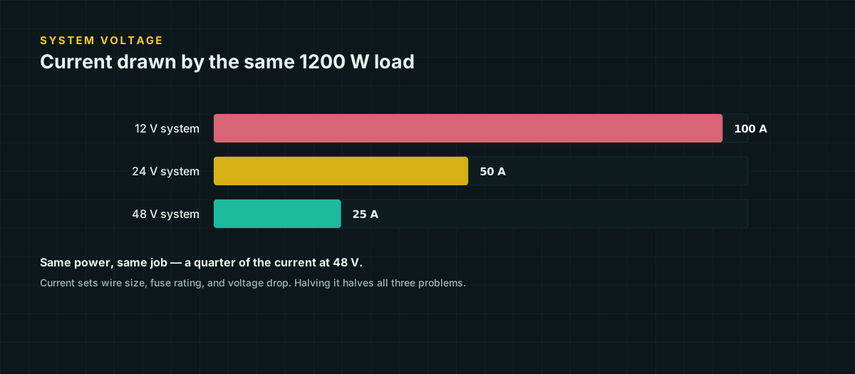
A 1200 W load sounds like one number, but it is not the number that decides your wire. Current is. At 12 V that load pulls 100 A; at 48 V it pulls 25 A. The copper that safely and efficiently carries 100 A is dramatically more expensive, stiffer, and harder to terminate than the copper that carries 25 A, and the gap gets worse once voltage drop enters the picture rather than just ampacity.
This is the entire argument for building at 24 V or 48 V instead of 12 V once a system grows past a few hundred watts. It is also, in a lot of small builds, not worth the trouble. This article works through the physics with real numbers, then gets specific about where each voltage actually wins.
Why current, not power, sets the wiring cost
Watts are what you shop for. Amps are what the copper has to survive. The relationship is Ohm’s law applied to power:
I = P / VDouble the system voltage for the same load and current is cut in half. Wire cost tracks current in two independent ways, and it is worth separating them because they do not scale the same:
Ampacity is a heat problem — how much current a conductor can carry before its insulation overheats. It scales roughly linearly with current: halve the current and you can drop one or two wire sizes and stay safe.
Voltage drop is a percentage-of-system problem, and this is where higher voltage pays off far more than ampacity alone suggests. The same current loss in volts is a much smaller percentage of a bigger number. Halving the current and doubling the reference voltage compounds into something better than either effect alone — which is the subject of the next section.
The quadratic relationship
Start from the drop formula, which is Ohm’s law over the round-trip circuit:
V_drop = 2 × L × I × R
drop % = (2 × L × I × R) / V_system × 100
Substitute I = P / V_system for a fixed load power P:
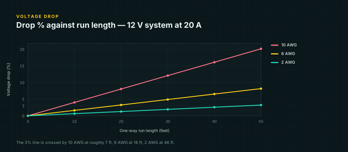
drop % = (2 × L × R × P) / V_system² × 100System voltage appears squared in the denominator. For the same wire, the same run length, and the same delivered power, doubling the system voltage does not halve the drop percentage — it quarters it. This is not a rule of thumb; it falls straight out of substituting one equation into another, and you can rerun the algebra yourself.
The table below shows it isn’t theoretical. It is the drop percentage for the same physical wire — 8 AWG, 20 ft one-way, 1200 W — at three voltages:
| System voltage | Current | Drop on 8 AWG, 20 ft one-way | Ratio to 12 V |
|---|---|---|---|
| 12 V | 100 A | 25.5% | 1x |
| 24 V | 50 A | 6.4% | 0.25x |
| 48 V | 25 A | 1.6% | 0.06x |
25.5 / 6.4 = 3.98, and 6.4 / 1.6 = 4.0. Each doubling of voltage divides the drop by almost exactly 4, matching the 2² in the formula. Full method and copper resistance figures for any wire size are in voltage drop tables for 12 V, 24 V, and 48 V systems.
Worked comparison: the same 1200 W load at three voltages
Suppose a 1200 W inverter sits 20 feet (one-way) from the battery bank — a realistic distance if the inverter lives in a different compartment or corner of a build than the battery. Ampacity sets a safety floor from NEC Table 310.16 at 75 °C; voltage drop then decides how much bigger the wire actually needs to be to keep losses under 3%.
| System voltage | Current | Min. wire by ampacity (75 °C) | Min. wire by 3% drop | Copper cross-section at the drop minimum |
|---|---|---|---|---|
| 12 V | 100 A | 2 AWG (115 A) | 4/0 AWG (2.0% actual) | 107.2 mm² |
| 24 V | 50 A | 8 AWG (50 A) | 4 AWG (2.6% actual) | 21.15 mm² |
| 48 V | 25 A | 12 AWG (25 A) | 10 AWG (2.5% actual) | 5.261 mm² |
Two things stand out. First, ampacity alone would let you run this load on 2 AWG at 12 V — but that wire would lose 6.5% of the system voltage over 20 feet, which is why the drop-driven minimum is three full sizes larger, at 4/0. Second, look at the last column: 107.2 mm² of copper at 12 V versus 5.261 mm² at 48 V is roughly a 20x difference in cross-sectional area for identical delivered power. That is the real cost of low voltage on anything beyond a short, light-current run — not the panels, not the controller, the copper.
At 48 V the ampacity minimum (12 AWG) and the drop minimum (10 AWG) are one size apart. That convergence is the underlying reason higher-voltage systems feel easier to wire: you are no longer fighting two separate constraints that disagree by a factor of five.
Component availability at each voltage
The physics favors higher voltage almost everywhere above a few hundred watts, but the physics is not the only thing you are shopping for.
12 V is the deepest market. Automotive and marine accessories — fridges, air compressors, cigarette-lighter sockets, USB chargers, water pumps — are built for it by default, because that is what vehicles run on. If a build leans on off-the-shelf 12 V accessories, that ecosystem is worth something real.
24 V sits in an awkward middle for hobbyist gear: common in larger inverters and some dedicated off-grid equipment, less common in cheap accessory-grade hardware. It is a reasonable step up when 12 V component current gets uncomfortable but a full 48 V rebuild isn’t warranted.
48 V is well served at the high end — stacked lithium packs, larger MPPT controllers, and split-phase or larger inverters increasingly default to it — but the inexpensive, hobbyist all-in-one units that dominate small DIY builds skew toward 12 V and 24 V. A small build chasing 48 V purely for the wire-size win can end up paying more for a controller and inverter than it saved on copper.
The 48 V question
If the quadratic relationship is this favorable, why doesn’t everything run at 48 V? Two reasons, and neither is really about the electricity.
The component ecosystem for small systems is thinner at 48 V, as above. And the safety margin that makes 12 V forgiving to a beginner — you can bridge the terminals with a wrench and mostly just get a spark and a bad day, not a shock — narrows as voltage climbs. 48 V DC is still commonly treated as a low-voltage, touch-safe design target in small systems, but the fault currents involved in a short across a large 48 V lithium bank are not something to get casual about. None of this changes the arithmetic above; it changes how much the arithmetic should weigh against everything else in the decision.
When 12 V is genuinely the right call
Higher voltage is not automatically correct. Three situations point straight at 12 V:
Small, short-run loads. A load under a few hundred watts on runs under ten feet often never reaches the point where drop forces expensive wire at 12 V in the first place. Building a 24 V system to solve a problem that doesn’t exist yet just adds a step-down or a second inverter class to shop for.
Automotive and marine accessory compatibility. If half the point of the build is running things designed for a vehicle electrical system, staying at 12 V avoids a pile of DC-DC converters between the battery and every accessory.
Single-battery systems. One 12 V battery is one battery to manage: one charge profile, no series balance to worry about, no risk of one cell group in the string aging differently from another. The moment you go to 24 V or 48 V with lead-acid or unmanaged cells, you take on a battery-balancing problem in exchange for a wiring win. A single well-chosen LiFePO4 battery with a built-in BMS reduces that risk, but it doesn’t eliminate the general principle: fewer series-connected cells is fewer things that can drift out of sync.
The conversion trap of mixing voltages
The mistake that catches people who have half-absorbed the voltage argument is tapping a lower voltage off part of a higher-voltage string instead of building a proper DC-DC converter into the design.
Picture two 12 V batteries wired in series to make a 24 V bank, with a 12 V load connected across just one of the two batteries to save the cost of a converter. It looks free. It is not. Every amp the 12 V tap draws comes from that one battery alone, while the 24 V loads draw evenly from both. The tapped battery cycles deeper than its partner on every single day the 12 V load runs. Charge controllers regulate the pack’s terminal voltage — the full 24 V — which tells them nothing about whether the two 12 V halves underneath are balanced. Over weeks, the tapped battery drifts further from its partner’s state of charge, ages faster, and eventually drags the whole bank’s usable capacity down to whichever half is worse off.
The fix, if a design genuinely needs both voltage domains, is a real DC-DC converter sized for the tapped load’s actual current — not a wire pulled off the string’s midpoint. It costs money and a little efficiency. It is cheaper than an unbalanced battery bank.
Choosing for your build
Work backward from your largest continuous load and your longest run, not from a voltage you liked on a forum post. Compute the current at each candidate voltage, check it against ampacity, then check the actual run against the 3% drop tables — the voltage drop reference has the full lookup by wire size and current at 12 V, 24 V, and 48 V. If ampacity and drop keep disagreeing by two or three wire sizes the way they do at 12 V in the worked example above, that disagreement is the system telling you it wants more voltage. If they already agree within a size, as they nearly do at 48 V, you have found the point of diminishing returns for going any higher.
Sources and further reading
Figures on this page are traceable to the published documents below. Where a standard is referenced, check the edition your local jurisdiction has adopted before relying on it.
- NEC Chapter 9, Table 8 — Conductor Properties (DC resistance, uncoated copper)NFPA 70, republished by buildmyowncabin.comResistance values referenced at 75 °C conductor temperature; used for every drop calculation below.
- NEC Table 310.16 — Allowable Ampacities of Insulated ConductorsNFPA 70, republished by wiresizes.comUsed for the 75 °C ampacity figures that set the safety-minimum wire size in the worked comparison.
- AWG to mm conversion calculator and referenceRapidTablesCross-sectional area figures used as the copper-cost proxy.