Solar Panel Placement: A Simple Shading Check Before You Mount
Why partial shading costs disproportionately more than the shaded area suggests, what bypass diodes do and do not fix, and how to survey a site for shade without special equipment.
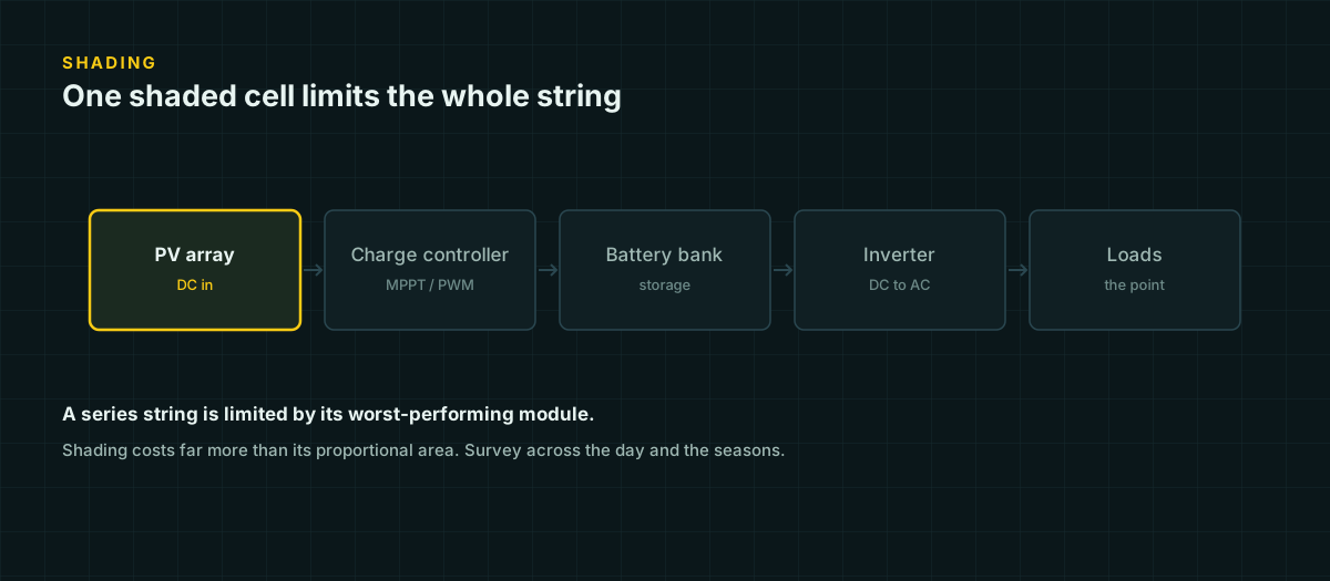
A single branch’s shadow across the corner of one panel looks like a small problem. Electrically, it usually isn’t. Solar cells inside a module are wired in series, and a series circuit carries the same current through every cell in the chain whether that cell is fully lit or sitting in shade. The shaded cell becomes a bottleneck for the whole string, not just for its own small patch of surface area. Placement decisions that look cosmetic on a rooftop sketch are actually circuit decisions, and this page is about checking them before the mounting hardware goes in, not after the production numbers come in low.
Why partial shading is disproportionate
Cells in series must carry identical current. A shaded cell produces less current than its unshaded neighbors, and neighbors cannot simply route around it — the series connection forces the string’s current down to whatever the weakest cell can supply. PVEducation’s explanation of series mismatch states the principle directly: “the output of the entire PV module under worst case conditions is determined by the solar cell with the lowest output.”
That’s why a shadow covering a small fraction of a module’s physical area can cost a disproportionate share of its power. It isn’t shading 5 percent of the surface and losing 5 percent of the output; it’s shading one weak link in a chain and losing whatever that link caps the whole chain to.
What bypass diodes rescue, and what they don’t
Bypass diodes exist specifically to limit the damage, not to prevent the power loss. A bypass diode sits in parallel with a group of cells (a “substring”), oriented so it does nothing during normal operation. When a cell in its substring is shaded and starts acting as a current bottleneck, the other cells in that substring force it into reverse bias — meaning it’s absorbing power instead of producing it, which shows up as heating rather than as electricity. PVEducation describes the consequence directly: without a way out, “the maximum reverse bias across the poor cell” would otherwise drive dangerous localized heating.
The diode gives the current a path around that shaded substring instead of through it. That protects the module from a hot spot. It does not recover the substring’s output — the current from the unshaded substrings is now flowing around a section of the module that’s contributing nothing. A typical 60-cell module with three substrings and one bypass diode per substring loses roughly a third of its rated output the moment any single cell in one substring is shaded seriously enough to trip that diode, regardless of whether it’s one cell or all twenty cells in that section that are shaded.
Module orientation changes how much you lose
The same physical shadow can cost very different amounts of power depending on how the module is mounted, because it determines which substrings the shadow actually crosses.
Most shading obstructions near ground level — fences, low walls, vehicles, vent stacks — cast horizontal shadows that creep upward from the bottom edge of an array as the sun gets lower. A module wired in landscape orientation has its substrings arranged as horizontal bands, so a low horizontal shadow typically only crosses into the bottom substring, tripping one bypass diode while the upper substrings keep producing. A module in portrait orientation has its substrings running the other way — a horizontal shadow at the bottom can clip a cell in every substring simultaneously, tripping all of them.
A solar-hardware technical write-up puts the mechanism this way: in landscape mounting, “the lowermost bypass diode is turned on. And the upper two rows of cells continue to output power,” whereas in portrait mounting under the same shading, “the circuit is broken. And all three rows of cells have no power output.” Same shadow, same panel, dramatically different result — purely from how it was rotated on the rack.
This matters most for exactly the obstructions you’re most likely to be checking for: low fixed objects near an array’s base, which is also where most amateur site surveys focus their attention first.
Surveying a site without a Solar Pathfinder
A dedicated shade-analysis instrument like a Solar Pathfinder reflects the whole sky dome and traces obstructions against a sun-path chart in one sitting. You don’t need one to do a competent manual check — you need to understand what the instrument is approximating and reproduce that with a few measurements.
Identify every obstruction first. Walk the site and list anything that could cast a shadow onto the proposed array location: trees (including how much they’ll grow before this decision matters again), your own roof features, chimneys, neighboring structures, power poles, even a future shed you haven’t built yet. This basic step — physically inspecting the site and cataloging every shade source before doing any math — is the same starting point published shading-analysis guides recommend.
Measure or estimate obstruction height and distance. For anything you can walk up to, this is a tape measure and pacing off the distance. For a neighbor’s roofline or a tall tree, an estimate against a known reference (your own roof height, a car’s length) is good enough for planning purposes.
Convert height and distance into a shadow reach using basic trigonometry. For a vertical obstruction of height h at solar altitude angle α, the shadow it casts extends a horizontal distance:
shadow length = h / tan(α)A 6 m tree at a 20° sun altitude throws a shadow 6 / tan(20°) = 6 / 0.364 ≈ 16.5 m. The same tree at a 45° sun altitude throws a shadow of only 6 / tan(45°) = 6 m. This is why the same obstruction is nearly harmless at midday in summer and a serious problem at low winter sun angles — the geometry, not the tree, is what changed.
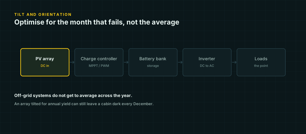
Check the worst case, not the average case. Solar altitude is lowest around the winter solstice and highest around the summer solstice, with the sun’s daily arc rising and falling between them through the year. An obstruction that clears the array easily in June can shade it for hours in December. If you only check shading on the day you happen to be standing on the roof, you’ve checked one arbitrary point on that curve — usually not the worst one. Plan for the solstice-adjacent low-sun case, since that’s also frequently when winter loads (heating-adjacent electronics, shorter days, more indoor time) push demand up while production is already at its yearly low.
Estimate solar noon altitude for the solstices at your latitude. A serviceable approximation for the sun’s altitude at true solar noon is:
altitude ≈ 90° − |latitude − declination|where declination is about +23.5° at the summer solstice and −23.5° at the winter solstice. At 40°N latitude, that gives a winter-solstice noon altitude of 90 − (40 + 23.5) = 26.5°, against a summer-solstice noon altitude of 90 − (40 − 23.5) = 73.5°. Plugging both into the shadow-length formula above for the same 6 m obstruction: 6 / tan(26.5°) ≈ 12.0 m in winter versus 6 / tan(73.5°) ≈ 1.8 m in summer — a nearly sevenfold difference in shadow reach from the same object, purely from the season. This is the arithmetic behind “check the winter case,” not just a rule of thumb to take on faith.
Reasoning about solar noon helps orient the whole exercise. At true solar noon — which is rarely the same as 12:00 on your clock, since it depends on your longitude within your time zone and shifts up to roughly 15 minutes through the year — the sun sits due south (in the northern hemisphere) at its highest point of the day. Anything that shades the array at solar noon in winter is shading it during what should be the day’s best production window, which makes it a higher priority to fix or work around than an obstruction that only bites in the last hour of daylight.
A low-tech survey toolkit
| Method | What it tells you | Equipment |
|---|---|---|
| Walk-and-list survey | Every candidate obstruction, before any math | Notebook, tape measure |
| Shadow-stick trigonometry | Reach of a specific obstruction at a given sun altitude | A stick, a tape measure, a protractor or angle app |
| Direct observation near the winter solstice | Real shading pattern under close-to-worst-case conditions | Nothing but timing |
| Phone compass + inclinometer app | Sight-line altitude/azimuth of an obstruction directly | A smartphone |
| Sketch across several visits (morning, solar noon, afternoon) | Coarse sun-path picture without any calculation | Nothing |
None of these replace a proper shading analysis for a permitted, financed, or performance-guaranteed installation. For a small DIY off-grid build, they’re enough to catch the obstructions that would otherwise only show up as “why is winter production so much worse than I planned for.”
String layout choices that limit the damage
Once you know a partial obstruction is unavoidable — a single vent pipe, an unmovable chimney — the wiring layout can contain the damage instead of spreading it.
Put the shaded module(s) in their own series string, separate from unshaded modules, if your array size and charge controller support multiple strings. That confines the mismatch loss to the modules that are actually shaded rather than dragging an entire long string down to the shaded module’s current. This is the same series-mismatch principle discussed above, applied deliberately: isolate the weak link instead of chaining it to strong ones. Our series versus parallel wiring guide covers how string configuration interacts with mismatch losses and controller voltage limits in more depth.
Before you mount anything
Treat a shading check as part of the electrical design, not a scouting formality. A five-minute walk with a tape measure and a bit of trigonometry, done before panels go on the roof, is cheap. Moving a mounted array — or discovering in December that a fence you didn’t measure costs a third of your winter production — is not. If the site has any unavoidable partial shading, decide the string layout around it deliberately rather than finding out the hard way which modules were sharing a string with the shaded one.
Sources and further reading
Figures on this page are traceable to the published documents below. Where a standard is referenced, check the edition your local jurisdiction has adopted before relying on it.
- Bypass DiodesPVEducation.orgSource for what bypass diodes do and the voltage/current mechanism behind partial shading.
- Mismatch EffectsPVEducation.orgSource for the principle that a series string's output is set by its worst-performing cell.
- The Impact of Landscape and Portrait Rows of Modules on Solar SystemWanhosSource for the landscape-vs-portrait bypass-diode substring comparison.
- How to Perform a Solar Shading Analysis for PV System DesignExpertCESource for the general site-survey framing (identify obstructions, trace sun position across the year); this page's own worked-out method is our own construction.