Cabin Solar Backup Power Wall: What to Plan Before Mounting Gear
Planning a cabin power wall for a building nobody occupies most months: self-discharge, freeze risk, seasonal battery chemistry, equipment layout, ventilation, surge loads, and the generator question.
A cabin power wall has a problem that a daily-use house or shed system does not: for most of the year, nobody is there. Self-discharge runs unchecked for months. Freeze risk compounds with state of charge instead of just ambient temperature. Loads that matter during an outage — a well pump, a propane furnace’s controller — are different in character from the loads that matter during a normal weekend, and sizing for one without the other produces a wall that works right up until it doesn’t.
This guide covers a small off-grid or backup cabin system. It is not a grid-tie or whole-home transfer guide. If the system connects to utility wiring, a breaker panel, generator transfer equipment, or a battery bank large enough to deliver serious fault current, that is licensed-electrician territory.
The problem with a building nobody lives in
Every battery loses charge sitting idle, chemistry aside. The rate is what differs, and over a multi-month unoccupied stretch the rate is the whole story.
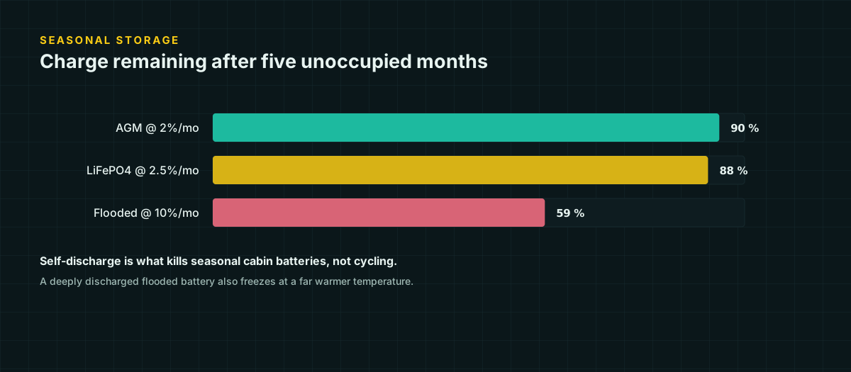
Battle Born states 2–3 percent per month self-discharge for its LiFePO4 line. Trojan’s published guidance for flooded lead-acid puts the figure at 5–15 percent per month, strongly temperature dependent. Self-discharge compounds monthly rather than subtracting in a straight line, so the arithmetic over a 5-month unoccupied winter looks like this, using the midpoint of each published range:
remaining fraction = (1 − monthly rate)^months

LiFePO4:  (1 − 0.025)^5 = 0.881  →  ~88% state of charge remains
Flooded:  (1 − 0.10)^5  = 0.590  →  ~59% state of charge remains
A LiFePO4 bank left over winter comes back to a nearly-full battery. A flooded bank comes back at roughly 59 percent — and a battery that arrives at 59 percent didn’t drop there on the last day of winter; it drifted down gradually, which matters for the next section.
Freeze risk isn’t just about the battery being cold
Flooded lead-acid electrolyte freezes at a temperature that depends on its state of charge, because the electrolyte is a sulfuric acid solution and its concentration — and therefore its freezing point — falls as the battery discharges. Per Trojan’s user guide: a fully charged cell at specific gravity 1.280 freezes around −68.9 °C, effectively never, in most North American winters. A nearly discharged cell at specific gravity 1.100 freezes around −7.2 °C — a temperature a genuinely cold winter night reaches without much trouble.
This is why the self-discharge math above is not a side note. A flooded battery that drifts down to 59 percent state of charge over an unoccupied winter has also drifted its freeze point upward, into a range the actual outdoor or unheated-cabin temperature can plausibly hit. A frozen lead-acid battery typically suffers cracked or buckled plates and case damage as the electrolyte expands — the failure is physical and usually not repairable. The rule that matters is not “don’t charge below freezing”; it’s “don’t let a battery sit discharged where it’s cold enough to freeze at its current state of charge,” and self-discharge is exactly what puts it there.
LiFePO4 has a different mechanism and a different failure mode. Below a manufacturer-specified charge temperature — Victron defaults to 5 °C, Battle Born’s documentation states 0 °C — lithium ions cannot intercalate into the graphite anode fast enough during charging and instead deposit as metallic lithium plating on the anode surface. This is irreversible capacity loss, and in worse cases the plated lithium can form dendrites that pierce the separator and cause an internal short. A quality BMS blocks charging below the cutoff to prevent this — which protects the battery, but means a cold, unattended cabin’s solar array may simply be unable to put any charge into the battery on the coldest mornings, regardless of how much sun is available.
Choosing a chemistry for seasonal use
Put the two mechanisms side by side and the seasonal-cabin decision becomes concrete rather than a brand preference.
LiFePO4 self-discharges slowly enough that a winter absence mostly resolves itself — the battery comes back close to where it was left. Its risk is the opposite of lead-acid’s: it may refuse to accept any charge at all on very cold mornings, which is a charging problem, not a damage problem, as long as the BMS is doing its job and blocking out-of-range charge current rather than accepting it. Confirm the specific unit’s charge cutoff temperature before relying on it through a cold snap, since the range across manufacturers runs from about 0 °C to 5 °C.
Flooded and AGM lead-acid self-discharge fast enough that an unoccupied winter is a real threat by itself, and that same self-discharge is what creates freeze exposure. A seasonal lead-acid installation needs one of: a small maintenance/float charger running continuously off grid power or a trickle solar panel sized just for maintenance, a battery brought to full charge and disconnected before a long absence, or physical relocation somewhere heated over winter. None of those apply to LiFePO4 in the same way.
For a cabin visited irregularly and left for weeks or months at a time, LiFePO4’s tolerance for being ignored is usually the deciding factor, independent of the usual cycle-life and weight arguments covered on the battery chemistry comparison page. Where lead-acid still wins is a cabin visited often enough that nobody worries about a multi-month gap, or a very cold, unheated site where the concern is charging in deep cold at all — a scenario neither chemistry handles gracefully, but where lead-acid’s failure mode (accept a slow trickle, sulfate slowly) is arguably more forgiving than lithium’s (refuse to charge at all until it warms up).
Laying out the equipment wall
The wall is not primarily an aesthetic decision. Component placement follows cable length and heat, in that order.
Every battery-fed conductor should be as short as the layout allows, for the reasons worked out in detail on the voltage drop tables page: drop is linear with distance, and low-voltage DC systems lose a startling fraction of delivered power to a few extra feet of cable. That single constraint mostly decides the layout — the inverter and any high-current DC loads belong immediately adjacent to the battery bank, not wherever looks tidiest on the wall.
Heat is the second constraint, and it runs in the opposite direction from “put everything close together.” Inverters and charge controllers generate real waste heat under load, and packing them tight against a battery bank raises the local ambient temperature the battery itself sees — which matters because both wire ampacity and battery charge behavior are temperature-dependent (see the dc wire ampacity page for how much a hot ambient derates a conductor). A workable layout keeps three zones distinct even in a small footprint:
- Battery zone — low, stable, away from any heat-generating equipment, with short protected cable exits.
- Power electronics zone — inverter, charge controller, monitoring — close enough for short cable runs, but with clear air space around each unit for the manufacturer’s stated ventilation clearance.
- Protection zone — fuses, breakers, disconnects, and labels, positioned to be reached and read without moving anything else first.
Ventilation: why it is not optional for lead-acid
Charging a flooded or AGM lead-acid battery electrolyzes some of its water content, releasing hydrogen and oxygen gas — more of it as the battery approaches full charge and during equalization charging. Hydrogen is flammable across a wide concentration range and explosive risk becomes real well before a sealed space would feel obviously “full of gas” by smell or visibility, since hydrogen is odorless and colorless. This is a basic property of how a lead-acid cell charges, not a manufacturer-specific claim, and it is the reason lead-acid battery enclosures need real ventilation to outside air rather than just a gap under a cabinet door.
LiFePO4 does not off-gas hydrogen during normal charging, which is one more reason it tolerates a sealed indoor enclosure better than lead-acid — but it is not exempt from ventilation planning altogether, since heat still needs somewhere to go and a thermal-runaway event, while rare with a competent BMS, still benefits from not being sealed into an unvented box.
Two different sizing problems: keeping the lights on vs. running a pump
“Backup power” for a cabin usually means two different things bundled into one project, and they size differently. Keeping lights, a router, and phone charging running during an outage is a modest, steady watt-hour problem — the kind the load audit method handles directly: small continuous and intermittent loads, summed into a daily Wh target.
Running a well pump, a pressure tank, or a compressor-based appliance during an outage is a different problem layered on top. These loads are often small in daily energy terms — a well pump might run a few minutes a day in total — but large in instantaneous power, and that instantaneous figure is what has to survive without tripping a breaker, sagging the bus voltage, or exceeding the inverter’s surge rating. A power wall sized only from daily watt-hours can have a battery that lasts for days on the “keep the lights on” loads and still fail the first time the pump kicks on, because nobody checked the second number.
Surge loads from pumps and compressors
Single-phase induction motors — the kind in well pumps, refrigeration compressors, and shop equipment — draw substantially more current for the first second or two of starting than they draw once running, because the rotor is stationary and offers far less impedance than it does once spinning. This starting current, commonly three to six times running current, is a general property of how induction motors start, not a specific manufacturer claim; the exact multiplier for any given pump depends on its design, and the nameplate locked-rotor amps (LRA) figure, where the manufacturer publishes one, is the only number specific enough to design around.
The consequence for a cabin power wall: the inverter must be rated for the pump’s surge, not just its running watts, and the battery-to-inverter conductor and fuse must be sized to survive that surge without nuisance-tripping — the general approach is covered on the DC fuse and breaker sizing page. A pump that runs at 800 W steady but starts at 3,000–4,000 W for a second is invisible in a daily watt-hour table and decisive in an inverter spec sheet. Check both.
The generator question
Many cabin systems eventually want a generator input — for a stretch of weather bad enough that solar alone can’t recover the battery, or simply as insurance. The planning-level decision is how the generator connects: a manual interlock kit or a transfer switch, both of which mechanically or electrically prevent the generator and the utility or inverter output from ever being connected to the same circuit simultaneously.
This is worth deciding early because it affects the power wall’s layout — a transfer switch or interlock needs its own accessible, labeled space near the protection zone — but the installation itself, anywhere it ties into an existing structure’s wiring or could allow backfeed onto a de-energized line, is licensed-electrician work. Backfeeding a supposedly dead circuit is one of the more dangerous mistakes an unqualified installation can make, both for the installer and for anyone working on what they believe is a de-energized line elsewhere on the same system.
Before you build
A cabin power wall succeeds or fails on assumptions nobody wrote down: how long the building actually sits empty, what the coldest realistic night looks like, and whether the loads that matter during an outage were sized by their peak draw or only their daily average. Answer those explicitly, choose a chemistry that matches the occupancy pattern rather than habit, and leave the layout enough space to be serviced by someone who wasn’t there when it was built. None of this replaces a local code review or an electrician’s sign-off once the system touches a structure’s wiring or scales past a small, low-voltage bank.
Sources and further reading
Figures on this page are traceable to the published documents below. Where a standard is referenced, check the edition your local jurisdiction has adopted before relying on it.
- 100Ah 12V Smart LiFePO4 Deep Cycle Battery — specificationsBattle Born BatteriesSource for the 2-3%/month LiFePO4 self-discharge figure.
- Understanding Temperature Limits of LiFePO4 BatteriesBattle Born Batteries, The Battle Born Educational SeriesSource for the lithium-plating mechanism behind low-temperature charge cutoffs.
- 12.8 & 25.6 Volt Lithium Iron Phosphate Batteries Smart — datasheetVictron EnergySource for the 5°C default LiFePO4 charge cutoff and 92% round-trip efficiency.
- Trojan User's GuideTrojan Battery CompanySource for flooded lead-acid electrolyte specific-gravity freeze points and temperature-compensated charging.